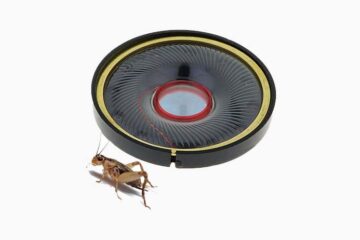
Nowadays portable LED tent lights can be purchased cheaply to provide ample lighting while hiking and camping overnight. Then it is only a simple matter of connecting the tent light to a mighty battery pack and light up your way and/or your tent. However, there is no fun in the lazy “click-buy-use” way. So, follow the instructions below to build your own customized portable LED tent light using a handful of cheap and readily available things.

To keep the project expansible, an Arduino microcontroller is used at the core of this LED tent light design. You will need the parts in the schematic. All are readily from a host of electronic parts distributors.
Now you can see the complete schematic of the Arduino LED Tent Light!
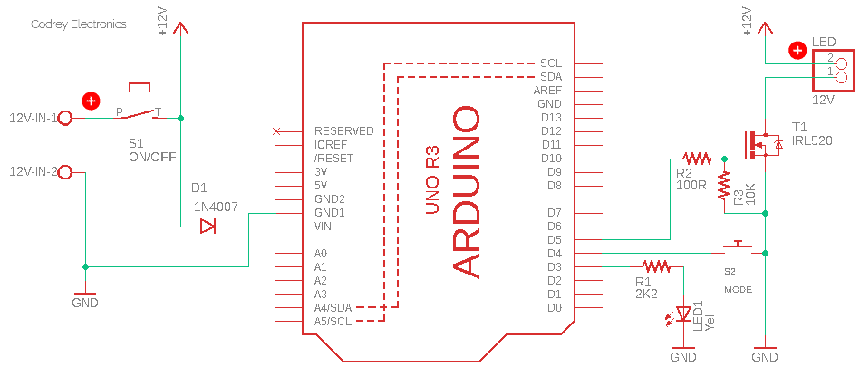
Here, one I/O of Arduino (D5) is used to control a Power MOSFET (T1) which in turn drive the LED tent light assembly. When the I/O pin is logic-high (H), the MOSFET switches on the LED tent light. By using Pulse Width Modulation (PWM) on the Arduino the brightness of the LEDs can be easily regulated.
This is in fact a multimode tent light, so, a momentary pushbutton switch (S2) is employed for mode selection. There’s also a status indicator lamp (LED1) that lets the user know the current mode of the tent light.
Here’s the code (Arduino Sketch) for the LED tent light. After you use the Arduino IDE to upload the code provided to your Arduino microcontroller, you will need to assemble the rest of the hardware, and enclose your successful build inside an appropriate rigid enclosure at last. In the end, it will be a pretty nice and useful device – guaranteed!
/*
 * Multimode LED Tent Light v1
 * A Portable Arduino LED Tent Light
 * T.K.Hareendran/07-2021
 */

// LED MODES:
// 0 = OFF
// 1 = Low Brightness
// 2 = Medium Brightness
// 3 = High/Full Brightness

int Number_of_Modes = 3;//Total 3 Modes
int LED_Mode = 0;//Initial Mode = OFF
int Status_LED = 3;//Status LED Pin D3
int DRV_OP = 5;//Tent Light LED Pin D5
int mode_buttonPin = 4;//Mode Button Pin D4
boolean buttonState = HIGH;

float MODE1_Bright = .10;// Low Light Level
float MODE2_Bright = .30;//Medium Light Level

int Flash_delay = 50;

void setup()
{

  pinMode(Status_LED, OUTPUT);
  pinMode(DRV_OP, OUTPUT);
  pinMode(mode_buttonPin, INPUT_PULLUP);// D4 Pull-up

  digitalWrite(Status_LED, 0);
  digitalWrite(DRV_OP, 0);

  // POST (Power On Self-Test)
  for (int i = 0; i <= 3; i++) {
    digitalWrite(Status_LED, 255);
    digitalWrite(DRV_OP, 255);
    delay(Flash_delay);
    digitalWrite(Status_LED, 0);
    digitalWrite(DRV_OP, 0);
    delay(Flash_delay);
  }
}

void mode_change_button() {
  int buttonState = digitalRead(mode_buttonPin);
  if (buttonState == LOW) {
    digitalWrite(Status_LED, 255);
    for (int x = 0; x < 25; x++) {
      digitalWrite(Status_LED, !digitalRead(Status_LED));
      delay(100);
    }

    if (LED_Mode >= Number_of_Modes)  {
      LED_Mode = 0;
    }
    else {
      LED_Mode = LED_Mode + 1;
    }


  }
}

void loop()  {

 // LED_Mode - OFF
  if (LED_Mode == 0) {
    analogWrite(Status_LED, 0);
    analogWrite(DRV_OP, 0);
  }

  // LED Mode - LOW
  if (LED_Mode == 1) {
    analogWrite(DRV_OP, (255 *  MODE1_Bright));
    for (int x = 0; x < LED_Mode; x++) {
      digitalWrite(Status_LED, 255);
      delay(100);
      digitalWrite(Status_LED, 0);
      delay(100);
    }
    delay(600);
  }

 // LED Mode - MEDIUM
  if (LED_Mode == 2) {
    analogWrite(DRV_OP, (255 *  MODE2_Bright));
    for (int x = 0; x < LED_Mode; x++) {
      digitalWrite(Status_LED, 255);
      delay(100);
      digitalWrite(Status_LED, 0);
      delay(100);
    }
    delay(600);
  }

  // LED Mode - HIGH
  if (LED_Mode == 3) {
    digitalWrite(DRV_OP, 255);
    for (int x = 0; x < LED_Mode; x++) {
      digitalWrite(Status_LED, 255);
      delay(100);
      digitalWrite(Status_LED, 0);
      delay(100);
    }
    delay(600);
  }

 mode_change_button();


}
It’s highly recommended to use a suitable TO-220 heatsink for the MOSFET, though it should be okay without it in certain cases.
The operation of this tent light is very simple and beautiful. During the initial power-up of the system, via the on/off switch S1, the status indicator (LED1) and the tent light LED will flash for a while. This quick strobe at the wake-up time is actually a power-on self-test (POST)!
Thereafter you can press the mode button (S2) to change the mode from off to low bright, medium bright, and full bright modes. The status indicator flashes quickly for each mode button action, and it also indicates the current mode by a unique flashing pattern for each active mode.
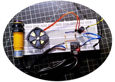
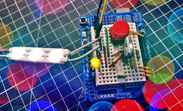
Before starting work on the final tent light, I decided to gain some experience and eliminate any errors by testing on a breadboard prototype. I used a 12V white LED module with a 12VDC/1A SMPS module to do that quick test. Needless to say, it worked well!
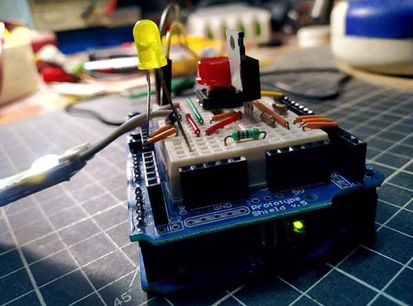
You can use any 12 volt LED module as the tent light LED, but the power source must be able to provide the power needed for its reliable operation. As such, a logic-level power MOSFET should be used here, as standard types do not work well in this circuit configuration. Mind it!
That’s all for now. Good Luck