 In this post, we are going to see how to build a secret button with Arduino! The basic idea of this little project is to use a single momentary pushbutton switch as a multifunction secret switch.
There are a number of ways to implement the multifunction button feature using a common microcontroller. The simplest method is a configuration for the user to hold down the button for different lengths of time so that the length of the hold time determines the final action. For example, when the user holds the button for 100mS and releases, something happens, and when the user holds it for 1000mS something different happens. Does this sound fun? If so, follow me!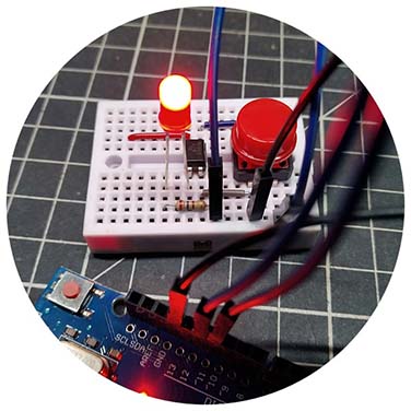
This is what you will need:
- Arduino Uno R3 Microcontroller
- Push-On Momentary Button Switch
- Red LED (5mm or 3mm)
- 270Ω ¼ W Resistor
- PC817 Optocoupler
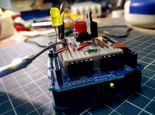
This is the wiring diagram of the entire hardware setup:
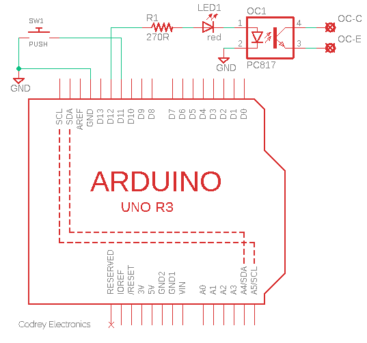
As you have noticed, the pushbutton switch SW1 is connected to D11 I/O of the Arduino Uno, while the D12 I/O is extended to the OC1 optocoupler through R1 and LED1. At this point, the output part of the optocoupler does nothing, but it will be useful later, we will see.
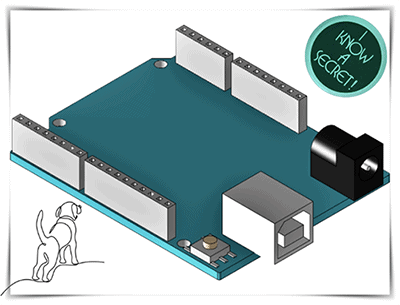
How to power your Arduino setup? It’s pretty simple as the Arduino is much more flexible, and can be powered via a number of ways.
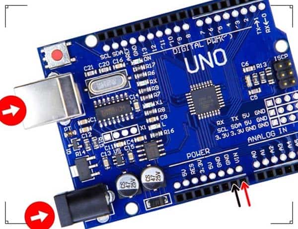
The easiest way is to power it through the onboard dc barrel jack. The operating voltage is recommended to be between 9V and 12VDC (500mA minimum), but remember the barrel plug must be center positive i.e., the middle pin of the plug has to be positive.
The Arduino also features a number of power input pins so you can power it up via those I/Os too (VIN/5V/3.3V). Again, the second simplest and safest method is to use the VIN pin to input 9-12VDC (instead of using the DC barrel jack or USB port). In any case, the dc voltage must be inputted with the correct polarity (VIN = +V).
This is the code (Arduino Sketch). Yes, a small piece of code that handles all of the needed things:
/* Arduino Secret Button v1 */

float buttonTime_milliseconds = 0;

int modeOne_milliseconds = 100;// Short Press 100mS
int modeTwo_milliseconds = 6000;// Long Press 6 Seconds
int buttonPin = 11; // Button Input D11
int outPin_Mode_1 = 13; // Short Press/Mode 1 Output D13
int outPin_Mode_2 = 12; // Long Press/Mode 2 Output D12

void setup() {
  pinMode(buttonPin, INPUT_PULLUP);// D11 Internal Pull-Up Enabled
  pinMode(outPin_Mode_1, OUTPUT);
  pinMode(outPin_Mode_2, OUTPUT);

}

void loop() {
  while (digitalRead(buttonPin) == LOW ) {
    delay(100);
    buttonTime_milliseconds = buttonTime_milliseconds + 100;
  }

  if (buttonTime_milliseconds >= modeTwo_milliseconds) {

    digitalWrite(outPin_Mode_2, HIGH);// D12 ON

  }

  else if (buttonTime_milliseconds >= modeOne_milliseconds) {

    digitalWrite(outPin_Mode_1, HIGH);// D13 ON

  }

  buttonTime_milliseconds = 0;

} // NOTE: USE ARDUINO RESET BUTTON TO RESET THE SYSTEM!
This code (as it seems to me) is lucid and straightforward. If it’s not straightforward to you, make sure to check out various Arduino tutorials and projects published here. Okay, just ignore it for a while and see what happens if you keep holding (and then releasing) the button.
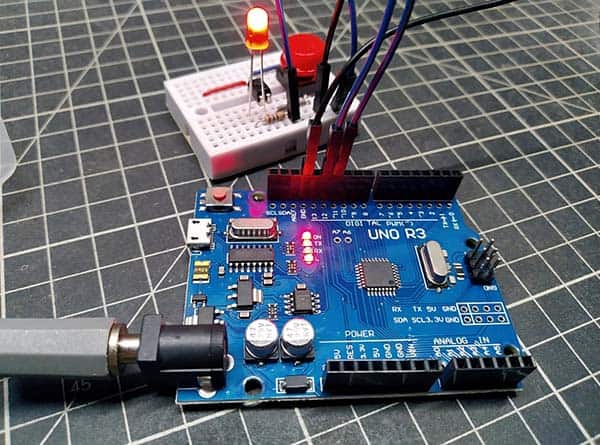
At first, let’s pretend we held the button for a short time (at least 100ms). When we release the button, the D13 output goes HIGH and the onboard LED lights up to indicate Mode1. It never
hurts to use the built-in LED for debugging purposes. It can be handy to know that the D13 output can also control an external circuitry if desired.
Next, if we hold the button for a long time (at least 6000ms), Mode2 gets executed when the button is released, and as a result, the D12 output goes HIGH to energize the optocoupler.
Sounds good, but what’s next with the “floating” optocoupler?
The optocoupler can be used to provide a pretty good galvanic-isolation i.e., it can effectively separate low-voltage and high-voltage segments of multipart circuitry. A standard optocoupler such as the PC817 (https://www.farnell.com/datasheets/73758.pdf) suggested here supports up to 5 kV of input-output isolation voltage!
The digital signal from the I/O of the microcontroller is used for switching the infrared LED (IRED) inside the optocoupler. Since The I/O of the microcontroller and the IRED in the optocoupler can handle a limited flow of current, it is recommended to use a current limiting resistor between the microcontroller’s I/O and the optocoupler’s input.
The way it works is simple – When a signal arrives, the LED within the optocoupler is turned on, and it illuminates the base of the integrated phototransistor. When the optically-coupled phototransistor is activated, the voltage between its collector and emitter falls to around 700mV and the associated circuit sees it as a logic LOW or HIGH-level transition according to the circuit configuration. For a detailed explanation of how to design optocoupler interfaces, see this post https://learnabout-electronics.org/Semiconductors/opto_52.php
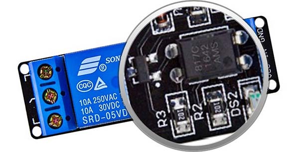
Needless to say, we can use an optocoupler together with a BJT to control an electromagnetic relay. Generally, electromagnetic and solid-state relays play a crucial role in today’s home automation and security projects.
That’s it! This multifunction button idea works nicely in a few of my recent security projects. In a few applications, it allowed me to simplify the user interfaces, and therefore fewer hardware.
At last, this is just an experimental project. So, you need to start your homework to build a featured secret button device for real-world applications. Let yourself be drawn by the stronger pull of that which you truly like!