Grey is the neutral achromatic color midway between white and black – Am I right? If you want to make something of yourself to detect the grey, let me give you a cheap and cheerful idea.
At first, keep your expectations low as the circuit is nothing but a sensor-head to detect grey with a common light dependent resistor – LDR – at its heart. Recently I missed a parcel from an online retailer in transit but my new client murmured repeatedly “hurry–it’s late … hurry–it’s late”. So, in a rush I built this grey tracker (in lieu of a pre-wired module) for his little semi-automatic robotic arm (worked well for him)!
The LDR
Yes we all know that LDRs (a.k.a photo-resistors) are light dependent resistors and its resistance decreases (usually < 1 KΩ from > 1 MΩ) with increasing light levels. Well, here’re a few more details for the most unaware hobbyists/novices:
- Response time of a standard LDR is in 2 ms–50 ms range which is much slower than a standard phototransistor
- They’re most sensitive to certain wavelengths. For example, the common CdS (photoconductive cadmium sulphide cell) types have peak spectral response at about 550 nm which is the green region of the visible spectrum
- All LDRs have memory effect/light history. This means if it has been stored for a long time in the light it will have a considerably higher light resistance than if it was stored for a long time in the dark
- Gamma values of 0.6 to 0.8 are quite usual for common type LDRs. “Gamma” is a measure of the slope of the resistance versus lux (a unit of illumination equal to 1 lumen per square meter)
- As far as I know, LDR possesses a spectral response similar to our eye – the human eye!
The Grey Tracker
![]()
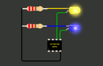
The non-contact grayscale tracker circuit shown above includes a 5mm LDR) and an a 5mm White LED. Once the circuit is powered on, its pin can be connected to analog read of a microcontroller and can measure the ambient light falling on the LDR. The circuit can be used in a variety of applications including grey scale approximation, close proximity detection, and bare ambient light detection. Pin definition of the module is given below:
- VCC: Positive rail of the circuit (+5V)
- GND: Ground rail of the circuit (0V)
- LED_ON: Control input of the White LED ( a TTL Logic-High input will turn on the LED)
- LDR_OUT: Analog signal output (Connect this raw output to an external microcontroller for identifying different levels of grayscale)
The simple example demonstrates basic application of the grey tracker with the help of an Arduino. Do connect LDR_OUT pin of the grey tracker to A0 input pin of Arduino, and read outputted values displayed in the Serial Monitor (LED_ON pin of the grey tracker is not used in this demo).
int LDR_Out = A0; //Analog pin A0
void setup(){
Serial.begin(9600);
}
void loop(){
int LDRData = analogRead(LDR_Out);
Serial.println(LDRData);
delay(500);
}
GUI?
Here, the Arduino analog input signal is converted at 10 bits of precision, that is, voltages between 0 and 5V are measured as integer numbers between 0 and 1023, with a nominal resolution of about 4.9 mV per step. As you might noticed, now a days there are many free (&costly) platforms available that can be used to create GUI for Arduino. What’s your opinion about using your Arduino to acquire signals from the grey tracker and transfer the data to your computer? For creating a great/advanced user interfaces you can try something (like LabVIEW) devised to help engineers without profound programming skills to configure and display measurements easily. I will come up with such a do-it-yourself project after a couple of weeks (promised). In the meantime, start thinking about your own way of an implementation, and give it a good try!
![]()

Just now I got a query from one Facebook friend about the 100K resistor at the base of the BC547 transistor. According to him, it’s not necessary!
Yes, base of the BJT is not a high impedance spot like a mosfet, but we might need to add a weak pull-down resistor to pull the base weakly down to a known level rather than just leaving it in a floating condition.
Refer first paragraph of the article. The circuit is designed as the part of a simple robotic arm project, where the transistor is driven by one GPIO of the existing uC. When the system is first turned on, GPIO of the said microcontroller has a Hi-Z state (for a while) often leaves the BJT in indeterminate state at that time. So, later I added the 100K resistor based on my client’s feedback to avoid the resultant blip in the drive mechanism.
As most designers might noticed, every circuit design will need individual valuation based on its real-world applications and situations. There’s no single practical resolution as individual circuit requirements (and observed anomalies) will prescribe whether we need certain inclusions or exclusions!