Do you like the idea of high-voltage electronic sparking devices, but don’t have the time or patience to learn the complex theory? Here’s a simple tutorial that can help you to make many high-voltage projects very easily and cheaply. Since the concept calls for a low-current source of high voltage dc, first of all let me give an introduction to dc voltage boosters/multipliers.
Voltage Booster/multiplier
Traditional and still broadly used dc voltage boosters/multipliers are based on a simple two-part diode-capacitor rectifier network. To understand its basic operation we can start off by referring a basic circuit, as follows:
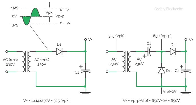
In the above half-wave rectifier dc power supply circuit (left side), AC230V is applied to the input and the circuit produces a positive output voltage of 325V, merely equals to the peak positive value of the transformer’s secondary voltage. In the next figure (right side) you can see the traditional two-part voltage multiplier circuit that gives a positive voltage output of 650V from an ac input of 230V provided by the secondary winding of the transformer. Note that, here the waveform’s peak output value equals the peak-to-peak value of the ac input voltage, and the final dc voltage output is equal to the peak-to-peak value (rather than the peak value) of the ac input voltage (actually sum of the peak-to-peak value and the common reference voltage).
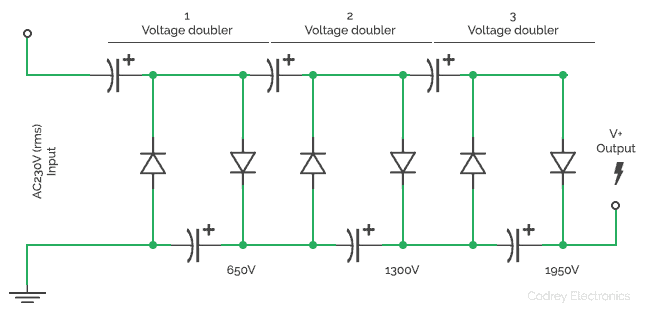
Although we can improve this idea to get a higher output by raising the reference voltage level, there’s a serious drawback. When we interconnect a number of the basic circuit to get various values of output voltage, each section generates an individual output while output of the first section acts as the voltage reference of the second section, and so on. This introduces a hitch as we need costly capacitors with absolute minimum voltage rating match with the voltage across output and ground rails of the occupied section. That’s quite speculative and impractical!
An easy solution is to try it up with the cheerful “Cockcroft-Walton” voltage multiplier circuit (see next figure). Note that a 10-stage version of this model, if driven by a 230V ac input, will give a dc output more than 6000V (6KV), but the components used in each stage just require a minimum voltage rating less than 1000V (1KV).
DIY Views
A quick & simple way to build a high-voltage generator circuit in order to gain some experience is shown below. It’s based the component values on what I had available, and there is plenty of scope for further tryouts (the number of sections you use will set the final output voltage). However, ensure that the components can handle requisite voltage levels safely. Capacitors should ideally be 2KV ceramic types (1nF, 10nF, and 100nF are usual values), and each diode must see a voltage well below its suggested rating.
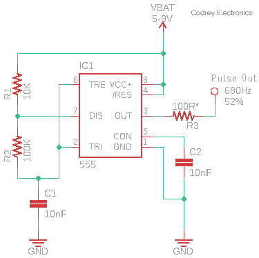
Top part of the figure is the circuit diagram of the Cockcroft-Walton (CW) voltage multiplier section, whereas bottom part depicts the ac voltage source circuit. In this section, a power mosfet (T1) is used to drive the step-up transformer (X1) but it needs a pulse input (~500Hz) from an external source. Any microcontroller or the venerable 555 timer chip can be configured to work as a pulse generator for driving the power mosfet. Give it a try…
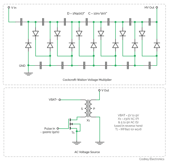
The trick used here is to drive a step-up transformer from the output of a low-voltage oscillator (free-running square wave generator) which can provide the required high-voltage ac on its output winding. The resultant ac voltage can then easily be multiplied with the help of the Cockcroft-Walton voltage multiplier mechanism. Keep in mind, output impedance of the Cockcroft-Walton voltage multiplier is rather high and it can hence render only small output currents. Below you can see the pulse generator circuit used for my prototype test.
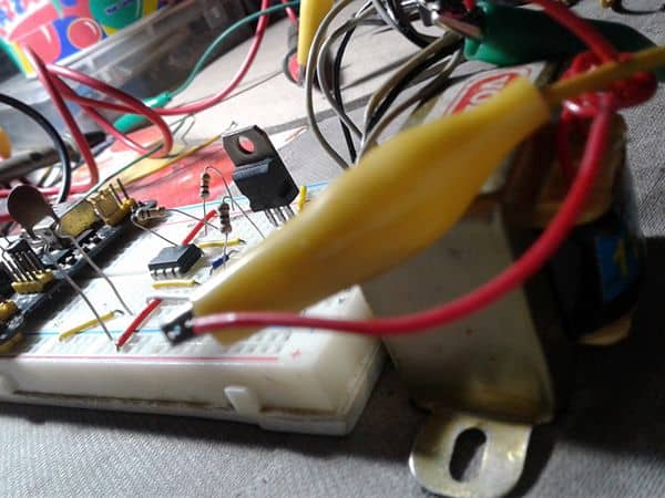
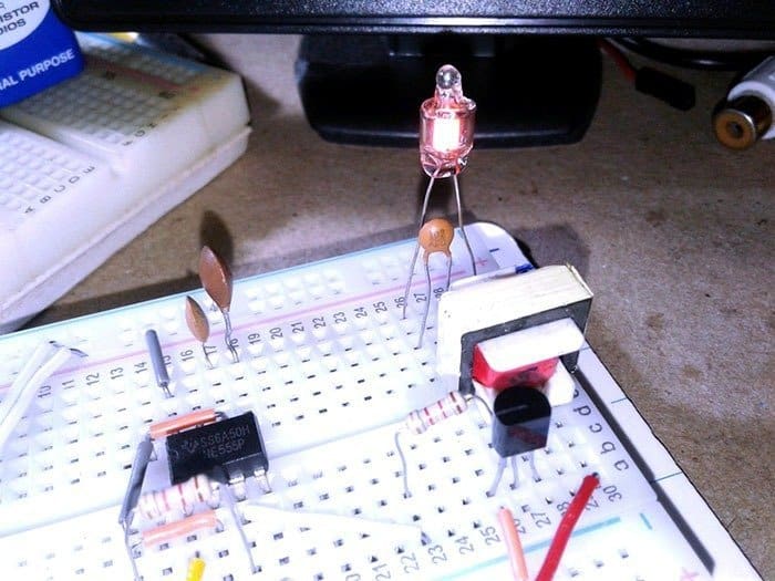
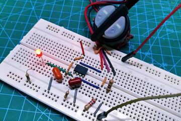
See a candid shot from my workbench while I was testing the breadboard prototype,
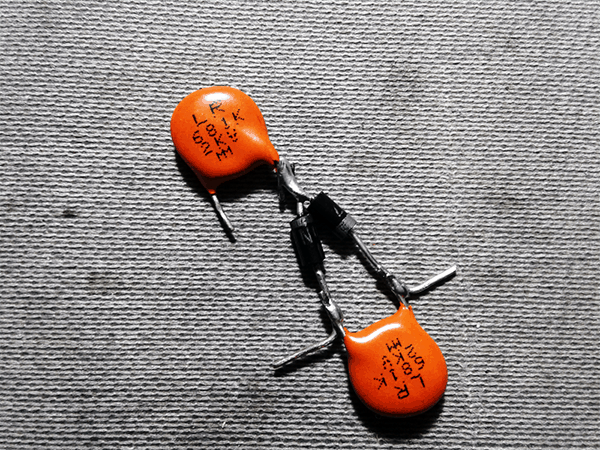
& build up of the voltage-doubler (with <1nF capacitors)
Warning: Although the experiments presented here have worked flawlessly in my lab, I cannot be held responsible for any wrongs that may occur to you or your instruments while following this article. Be prepared for dangerous consequences and emergencies!
trying to leave comment re digital pulse counter.. comment not appearing on the page..
maybe forum different to others..
Hello
Dear sir.
I built your schematic with IRF840 and 12-220V transformer.
But my voltage is 25V!
hasa: Since the oscillator frequency is around 700Hz, you should use a True-RMS multimeter (or oscilloscope) to get an accurate AC output voltage value (Vout). Also remember to multiply the resultant AC voltage (Vout) with the help of the suggested Cockcroft-Walton voltage multiplier to get the final high voltage output (HVout). Hope this helps. Thank You!
Thanks for your answering.
Can you tell me value of R3 in 555 schematic (out of timer)? I think i should change 100R because my IRF840 is very cold, i think it’s not switching.
And please tell me ampere of your battery?
I have two models battery, 12V-4.5A sealed acid and Li-ION polymer 12v-10000mAh.
I replaced your IRF840 with two models, IRF540 and IRFZ44N.
The two models worked but their power is very very high so that my batteries goes down after a few second.
hasa: This post was published around 4 years ago, so I can not test or modify its prototype right now. Sorry about that. Also, I am extremely busy with countless projects.
You can continue experimenting in your own way to get optimal results from your specific prototype. Good luck!
Thanks dear sir.
Do you remember out ampere of your transformer? for exp, 300mAh, 500mAh?
I tested your schematic over a 1-ampere transformer and it didn’t work.
Maybe it’s because of ampere of my transformer.
Thanks for your supporting.