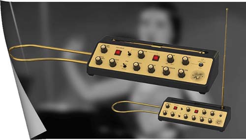
The theremin is an electronic musical instrument with two metal rods (antennas) used to control pitch and amplitude by the human operator using hand gestures. The left rod (a horizontal hoop) reduces the amplitude as the left hand is moved closer to it, while the right rod (a vertical pole) increases the pitch as the right hand is moved towards it (https://www.doctormix.com/blog/the-theremin-explained).
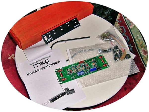
Nowadays, both Theremin instruments and do-it-yourself kits are available (see below). Some cheap Theremins however may only have pitch control and may be harder to play accurately because of a relatively non-linear relationship between the distance of the hand and resultant pitch, as well as a relatively short span of hand-to-antenna distance for producing the available range of pitch (https://www.wikiwand.com/en/Theremin).
Theremin is one of the most fascinating musical instruments ever made, mainly because of its quite odd and funny playing method. Although several serious Theremin builds are possible, this little post is about the construction of a nice and simple Light/Optical Theremin based on an Arduino microcontroller.
The do-it-yourself project description, together with schematics and source code, can be found below. With simplicity in mind, the Theremin project presented at this point will only handle pitch modulation.
This is the schematic of the Arduino Optical Theremin (v1):
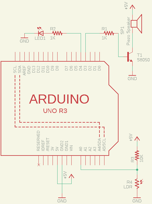
The key components required are:
- Arduino Uno
- S8050 Transistor
- Red LED
- 16Ω Electromagnetic Buzzer
- GL5528 LDR
- 1K and 10K ¼ w Resistors
- 9V/600mAh Li-ion Rechargeable battery
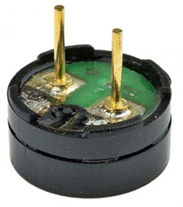
First off, note that the sounder is an electromagnetic buzzer – not an active piezo buzzer – you can commonly find in quartz alarm clocks and computer motherboards (https://islproducts.com/design-note/piezo-buzzers-vs-magnetic-buzzers/).
This is a sample datasheet https://docs.rs-online.com/3e45/0900766b8105f103.pdf
If you intend to use a separate audio amplifier (maybe a powered speaker), you can leave this part out, and take steps further to add the external audio amplifier which will make your tone output much louder. Remember, do not connect the tone output pin directly to an external audio input because the output voltage is considerably higher than the standard “line level” voltages (https://en.wikipedia.org/wiki/Line_level), and can damage the audio system. Often, you need to use a coupling capacitor in line with the output path to block the dc signal from entering the second element (and thus only passes the ac signal).
As an aside, be aware that the operating voltage of a common 9V Li-ion rechargeable battery is 6.0V~8.4V while its nominal output is 7.4V (https://www.codrey.com/electronics/9v-rechargeable-battery-right-wrong/).
Below is the simple code of the Optical Theremin, which’s actually for the Arduino Uno but can also be ported to other Arduino boards.
const int speakerPin = 3;
const int LEDpin = 4;
const int photosensorPin = A0;

int lightMIN = 1023;
int lightMAX = 0;

int sensorValue = 0;
int pitch = 0;

unsigned long previousMillis = 0;
const long interval = 6000;

void setup()
{
  pinMode(speakerPin, OUTPUT);
  /*Calibrate*/
  previousMillis = millis();
  digitalWrite(LEDpin, HIGH);
  while (millis() - previousMillis <= interval) {
    sensorValue = analogRead(photosensorPin);
    if (sensorValue > lightMAX) {
      lightMAX = sensorValue;
    }
    if (sensorValue < lightMIN) {
      lightMIN = sensorValue;
    }
  }
  digitalWrite(LEDpin, LOW);
}

void loop()
{
  /*Play*/
  sensorValue = analogRead(photosensorPin);
  pitch = map(sensorValue, lightMIN, lightMAX, 50, 6000);
  if (pitch > 50) {
    tone(speakerPin, pitch, 20);
  }
  delay(10);
}
When the setup is powered up, the LED will light up, and you’ll get a few seconds (six seconds by default) to calibrate the detection range of the photoresistor. Then you need to wave your hands up and down on top of the photoresistor to calibrate it. After the calibration process, the LED will go out and then you can swing your hands on the photoresistor to play. The self-calibration feature is added deliberately to help you because you may be in a different light environment each time you play your Theremin (you can tweak it as you wish).
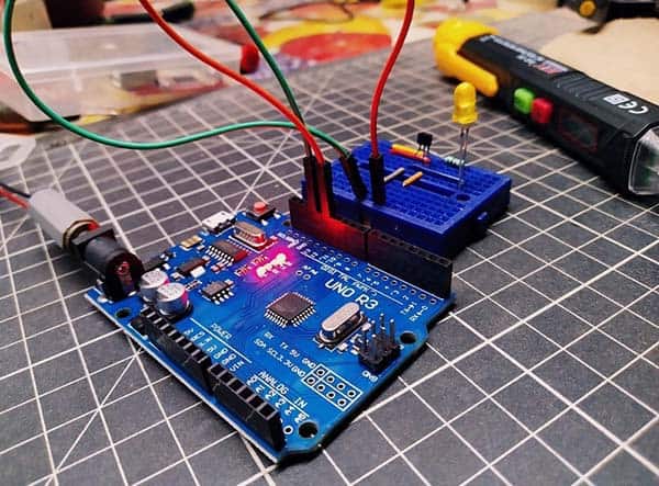
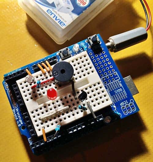
This is the first breadboard design. As you see in the below image, I used an Arduino Prototyping Shield to make the construction easier.
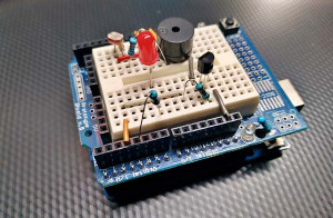
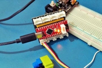
Plus, a couple more snaps:
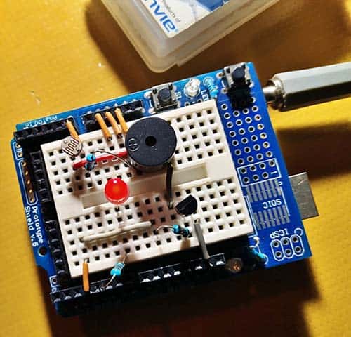
There you go! Now we’ve a simple Light Theremin that’s ready to go on the road!
What’s Next?
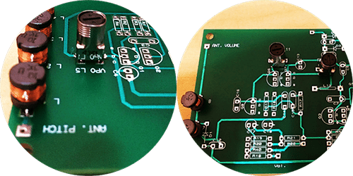
Since I intend to make a copy of the commercial Theremin, I decided not to go ahead with a permanent version of this simple Theremin. Note that, the antennas in such a Theremin, naturally, are not antennas. They’re one plate of a capacitor, the performer’s body and hands forming the other plate of an air-spaced variable capacitor. Thus, by moving the player’s hand nearer and farther from the antennas, the capacitance changes accordingly, and it takes place within the variable frequency oscillator (VFO) portion of the Theremin’s internal circuitry.
OK, so what exactly does this mean? Simple! A Theremin makes sound by mixing the signals from two oscillators – one is fixed and the other can be varied by the capacitance between the player’s hand and the “pitch” antenna. The mixed signals go through a nonlinear filter which produces the beat frequency which’s equal to the difference between the two oscillators, which you actually hear. The closer the hand to the antenna, the greater the capacitance between them, the further the variable oscillator frequency is drifted and the higher the beat frequency and hence the pitch of the tone you hear. The volume adjustment can also be done by a similar setup in which the beat frequency controls the gain of an amplifier.
A later post will explain how to build a commercial Theremin. Until then, Happy Tinkering!