A capacitive proximity sensor is a non-contact device that can detect the presence or absence of an object in its close vicinity. It utilizes the electrical property of capacitance and the change of capacitance based on a change in the electrical field around the active zone of the proximity sensor. The following guide provides the construction details of a tricky touch sensor/ capacitive proximity sensor centered on an Arduino Uno microcontroller!
![]()
Okay, let’s start with a canonical code…
Source of inspiration https://playground.arduino.cc/Main/CapacitiveSensor/
#define INDICATOR  13
#define SETPOINT   3

int capD;

void setup()
{
  pinMode(INDICATOR, OUTPUT);
  pinMode(9, OUTPUT);
  pinMode(10, INPUT);
}

void loop()
{
  capD = 0;


  digitalWrite(9, HIGH);
  int val = digitalRead(10);
  while (val != HIGH) {
    capD++;
    val = digitalRead(10);
  }
  delay(1);

  digitalWrite(9, LOW);

  if (capD > SETPOINT)
    digitalWrite(INDICATOR, HIGH);
  else
    digitalWrite(INDICATOR,  LOW);
}
Now to a quick breakdown of the above Arduino Sketch.
As you can see, this basic code used just three I/Os of the Arduino Uno board – the first two as the proximity sensor pins (one for input and the other for output), and the third one as the signal output pin. The D13 I/O pin is selected on purpose for the signal output pin because it’s hard-wired to the “hello world” LED (L) in the Arduino Uno board.
When the proximity sensor output at D9 transits from a LOW state to the HIGH state, it keeps the D10 input state LOW for a little while. This interval increases if the “antenna” (bare aluminium or copper wire) wired on D10 detects a touch/close proximity and vice versa.
The time interval is defined by T = R x C, where:
T = Time Interval
R = Resistance of R1
C = Antenna Capacitance (plus the capacitance of the conductive object in contact with it)
Look, at the start of each main loop cycle in this code, the value of the variable “capD” will be 0. Then for the time interval, the value at D10 returns LOW, “capD” increments. This results in “capD” being barely incremented if the antenna is not in contact with a conductive object.
But, as soon as someone touches or something approaches the antenna, the value quickly increments because of the longer time interval. So, when the “capD” value is above the setpoint, it means the antenna just detected a touch/close proximity (the value of the setpoint determines how sensitive the touch/proximity detector setup is to be).
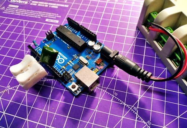
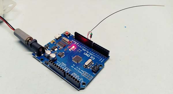
Below is the hardware setup diagram.
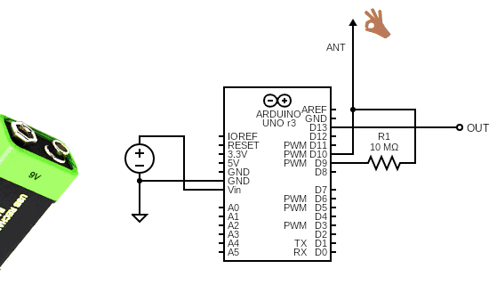
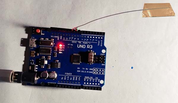
This setup can be easily powered by a 6F22 9V battery. And, as pointed out before, you need to connect a short bare copper or aluminium wire to the sensor input pin as the antenna. Likewise, a 1M to 10M resistor (R1) is needed between the sensor input (D10) and output (D9) pins. I conducted my quick tests with a 10MΩ resistor as R1.
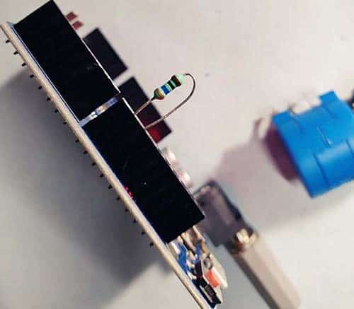
My antenna (touch sensor) at that time was a 15cm long bare aluminium wire (see below) but later I tried an insulated wire with a small uncovered area at its tip successfully. Note that you can use lower values of R1 (1M) for absolute touch to activate the system, but with a 10M resistor it should start to respond 2-4 inches away!
Obviously, there might be a lot of jitter as well as environmental impacts that might make the capacitance value vary enormously. This can be fine-tuned by using a smoothing filter in the code i.e., by reading the capacitance value for a number of times and then averaging the values. Give it a try!
While on the topic, capacitive proximity sensing techniques are based on human or object interference with electrostatic fields. Most capacitive sensors compensate for larger, static system capacitance and focus on accurately measuring small capacitive differences. The ability to measure minute differences is the key element of non-touch proximity detection.
And, the common approach in touch sensing is to measure the absolute capacitance of the load at the sensor input pin and compare it to a threshold value to decide if a touch has occurred (a simple algorithm can be implemented that enables detection using fixed thresholds but multiple setpoints are possible).
Seemingly, filtering can avoid false triggering by helping to eliminate undesired capacitance changes due to high levels of electromagnetic interference which might have a different profile than those caused by a valid input.
Okay, check back later for a theoretic article!
In conclusion, the real intention behind this writeup is just to show you how to build a crude Arduino Touch Sensor/Capacitive Proximity Sensor without using any dedicated proximity sensor modules. Here, the setup turns two Arduino I/Os into a capacitive sensor that can sense the electrical capacitance of the human body. All the simplistic setup requires is a high-value resistor and of course a piece of wire (with an optional slice of copper or aluminium shielding foil on its end) as the antenna. The proposed setup is able to sense a hand or body inches away from the antenna.
Anyway, there’re likely to be silly bugs and bad design practices. I’ve checked it all, my prototype runs fine for a long time so nothing major wrong with it at least. Let me know in the comments what you think!