This little post is about the quite popular FOTEK Solid State Relay (FOTEK SSR).
First note that FOTEK is a well-known brand in China and a FOTEK SSR will last a long time. But sadly, there are many counterfeits that are very similar to the original product, but not capable of operating at the specified capacity. Well, I will explain more about it in another post, let’s go ahead with my quick guide this time!
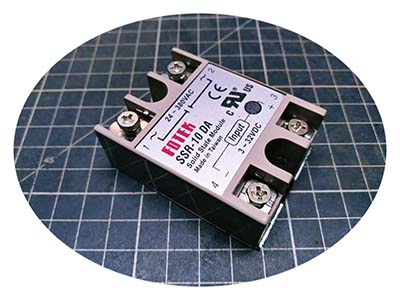
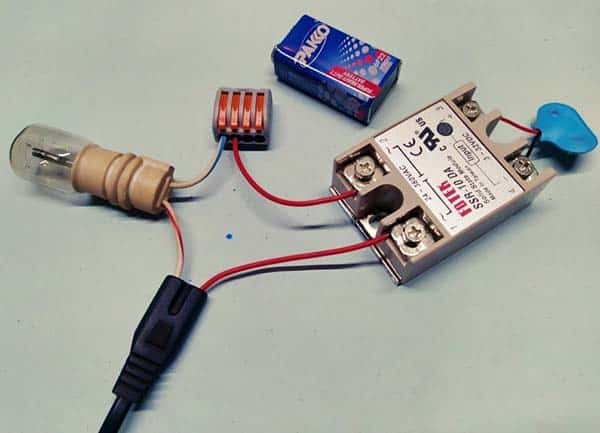
The part under the spotlight is the FOTEK SSR-10 DA which is a 10A AC Solid State Relay (see above photo). Here’re its technical specifications:
- Input Voltage: 3 to 32VDC
- ON/OFF Voltage: ON>2.4V , OFF<1.0V
- Trigger Current: 7.5mA/12V
- Control Method: Zero Cross (ZC) Trigger
- Output Voltage: 24 to 380VAC
- Rated Load Current: 10A
- Voltage Drop: 6V/25°C
- Leakage Current: 0mA
- Response Time: ON<10ms , OFF<10ms
- Dielectric Strength: Over 2.5KVAC/1min.
- Isolation Strength: Over 50MΩ/500VDC
- Operating Temperature: -20°C to +80°C
- Housing Materia: ABS
- Weight: 105g
This is a “terminal type” SSR. That’s okay, but what does that “SSR-10 DA” mean?
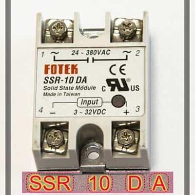
When I looked on the internet, it quickly became clear what was behind that particular code. So that information is given below.
- SSR = SINGLE PHASE SOLID STATE RELAY (PRODUCT TYPE)
- 10 = 10A (RATED OUTPUT CURRENT)
- D = DC 3-32V (ON/OFF INPUT VOLTAGE)
- A = AC (OUTPUT VOLTAGE TYPE)
- ⌂ = OUTPUT VOLTAGE RANGE*
* If there is no fifth letter (Usually H), that SSR features a nonstandard type output voltage (24-380VAC).
As a quick refresher, in the zero cross trigger method, the output switches only on the zero cross point of the sinewave (look below). Note that this method is particularly appropriate for controlling resistive, capacitive, and non-saturated inductive loads.

However, one downside to the zero crossing method is that you cannot easily use such an SSR for pulse-width modulated (PWM) dimming because it will maintain its state until the AC output waveform crosses zero on its own (what you needed then is a random turn-on type solid state relay).
In my first test, I connected the output of a digital lab power supply, dialed to 9V, to the inputs of my SSR. As you can see, its input current (trigger current) consumption is around 7mA at 9VDC.
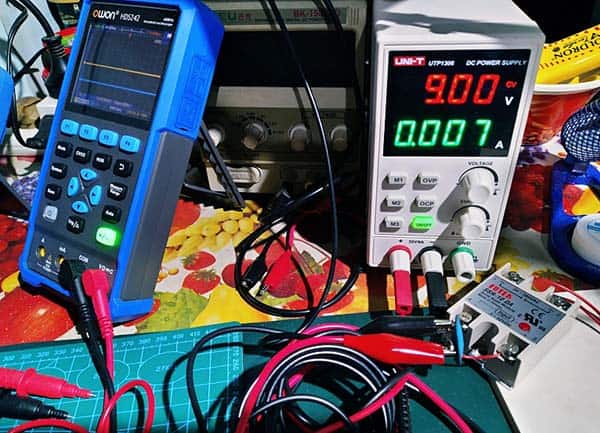
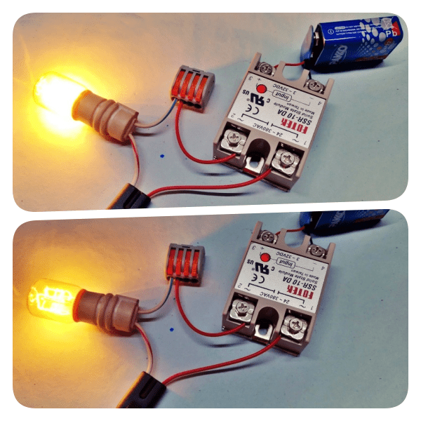
Later I used a 6F22 9V battery as the trigger voltage source.
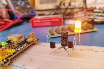
When the trigger input supply was applied, the load (a small incandescent lamp) turned on, and so did the indicator light on the SSR. Although it’s a trivial test, I was happy with the outcome. It worked fine!
In most cases, you can use a microcontroller‘s GPIO to drive the FOTEK SSR directly, but a BJT-based additional driver circuit is good from a safety standpoint. The image below illustrates some of the ideas suggested by FOTEK. I recently tested the first trick with a Digispark microcontroller successfully!

Last, of all, an SSR has a few crotchets but seems like a cheerful alternative to the electromechanical relay in today’s compact IoT projects.
I’m sure that fake FOTEK SSRs are extremely common. Typically, a counterfeit FOTEK SSR will fail miserably at currents significantly lower than its rated current, even when used with a recommended heatsink. As advice based on my experience, even if your FOTEK SSR seems genuine, simply assume it’s not and run it under 50% of its rated capacity!
In another post, I will try to cover the following FOTEK solid state relays that are not so familiar to many beginners.
- Three-phase SSRs
- Linear Control (4-20mA input) SSRs
- Adjustable (variable resistance/trimmer input) SSRs
- DC to DC SSRs
- AC to AC SSRs
Good luck, and see you next week.