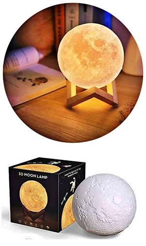
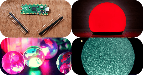
I made this as a Christmas present last year. This is a small color-changing RGB LED orb light controlled by Raspberry Pi Pico. I got the inspiration for this project from the Chinese-made USB-rechargeable color-changing LED moon lamp shown here.
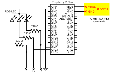
The Raspberry Pi Pico was deliberately chosen because I wanted to enhance the basic design later without making any major changes to the existent hardware. Below is the schematic of my Raspberry Pi Pico RGB Orb Light (v1).
Pico Power Supply
The Raspberry Pi Pico is in fact a 3.3V device, however, it can be powered by a range of power sources (thanks to a built-in voltage converter and regulator).
Raspberry Pi Pico Datasheet https://datasheets.raspberrypi.com/pico/pico-datasheet.pdf
All of the power supply pins are located close to the micro-USB connector.
- VBUS – This is the micro-USB input voltage linked to the micro-USB port. If you use a micro-USB power supply, this pin will be nominally at 5V, or 0V if the USB power source is not connected
- VSYS – This is the main system input voltage pin that can handle dc voltages from circa 1.8V to 5.5V.The onboard voltage converter will change it to 3.3V for the Pico.
- 3V3– This is a 3.3V output from the Pico’s internal voltage regulator. This pin can be used to power additional components, providing you keep the load well under 300mA.
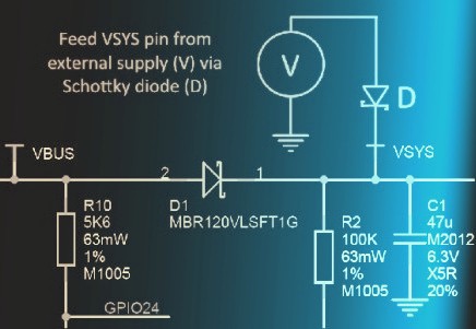
In a nutshell, the easiest way to power Pico is to plug in the micro-USB, which will power VSYS, and therefore the system, from the 5V USB VBUS voltage, via D1 (so VSYS becomes VBUS minus the Schottky diode drop). If the USB port is the only power source, VSYS and VBUS can be safely shorted together to eliminate the Schottky diode drop (which improves efficiency and reduces ripple on VSYS). If the USB port is not going to be used, it’s safe to power Pico by connecting VSYS to your preferred power source in the range of 1.8V to 5.5V.
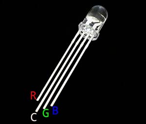
RGB LED/Module: The light source of this project is a common-cathode 5mm RGB LED. Water clear or diffused type RGB LED can be used here. A common-cathode RGB LED has four leads: three short anode leads – one for each of the three component colors (Red, Green, and Blue) and one long lead for the cathode.
Here’s the pinout of a 5mm common-cathode RGB LED. There may be variants, so identify the pins yourself before using them in your project.
In a regular common-cathode RGB LED, its R-LED usually has a minimum forward voltage of 1.9V (VF @20mA IF) while it’s 2.9V for the G-LED and B-LED. According to datasheets, you must use a protective resistor in series with each anode to limit the operating current.
Kitronik offers a handy LED resistor value calculator to help you choose the right resistor for your project https://kitronik.co.uk/blogs/resources/led-resistor-value-calculator
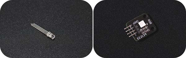
Needless to say, a common-cathode RGB LED module with or without built-in series resistors can also be used here if you know what you’re doing!
Pico Example Code: I’ve tailored several codes for MicroPython users so far. Below you’ll see the simplest one. You can improve this example code for example by creating functions for the different LED colors and maybe adding the other colors using different combinations of the R-G-B values.
If you are new to the world of Raspberry Pi Pico, take a moment to read previous posts published here. In keeping with Raspberry Pi tradition, Pico has good documentation and great community support too. Also, if anything isn’t clear let me know.
from machine import Pin
import utime

red = Pin(13, Pin.OUT)
green = Pin(14, Pin.OUT)
blue = Pin(15, Pin.OUT)

while True:
    red.value(0)
    green.value(0)
    blue.value(0)
    utime.sleep(2)

    red.value(1)
    green.value(0)
    blue.value(0)
    utime.sleep(2)

    red.value(0)
    green.value(1)
    blue.value(0)
    utime.sleep(2)

    red.value(0)
    green.value(0)
    blue.value(1)
    utime.sleep(2)
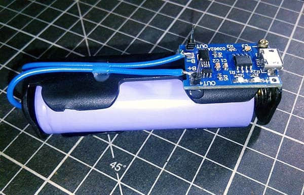
Orb Light Battery: Some time ago I built a 1S lithium-ion battery power pack for another project. It’s nothing but the simple combination of a 1S lithium-ion battery (3.7V/2200mAh) and a 1S lithium-ion battery charger module (TP4056). I used the same compact power source at this time as it’s no longer needed for the project set aside.
Orb Light Shell: At this point, you should create the enclosure part of the project. For that, you can make a beautiful 3D printed globe. Or you can try any ready-made plastic/rubber ball or something similar that suits you. See the pictures below for inspiration.
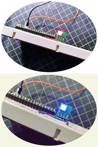
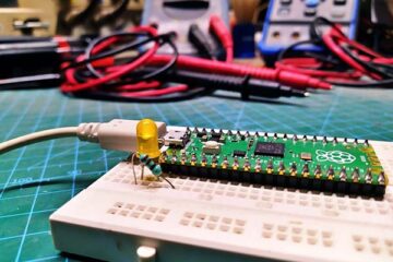
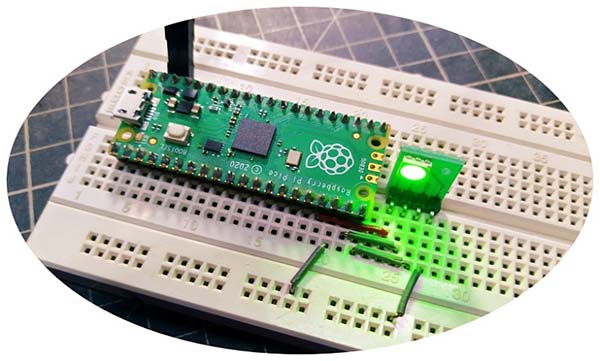
And finally, here you can find a casual snap of my breadboarded prototype. It’s nothing more than a crude test build that guarantees that my simple idea will work as expected!
Going Forward…
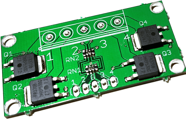
The next idea in the queue is to use the Raspberry Pi Pico to drive 4-channel LED strips (red-green-blue-white) through pulse width modulation so I can use that setting as a fantastic garden/lawn festival light controller. However, this requires an external multichannel lamp driver circuitry.
MOSFETs can be used for controlling large loads from a microcontroller. As technology has advanced, and processor voltages have moved to 3.3V and below, logic-level MOSFETs have become widely available which will turn on with lower gate voltages.
As an example, this is a 4-channel MOSFET breakout board designed for use with gate voltages as low as 2.8V. Therefore, this module is also suitable for Raspberry Pi Pico projects.
That’s all for now. This is of course not great, but quite interesting for me, and for some novices too!