This title is a bit exaggerated, I agree, but the following writeup is actually about controlling LEDs and Buzzers using Raspberry Pi Pico. At first, this may seem like a simple topic, but here you will find some pointers (maybe more useful for novices) that are not often discussed. So read on…
The Raspberry Pi Pico board has an onboard LED. Getting the built-in LED on GP25 to light is pretty easy with the below code. Yes, this gives you a simple “Hello World” flashing LED.
import machine
import utime

#Setup the onboard LED Pin GP25 as an output
LED = machine.Pin(25,machine.Pin.OUT)

while True:
    LED.value(1)
    utime.sleep_ms(500)
    LED.value(0)
    utime.sleep_ms(500)
Well, the next code will help you add a single pushbutton switch to turn on and off the onboard LED.
import machine
#Setup the onboard LED Pin GP25 as an output
LED = machine.Pin(25,machine.Pin.OUT)
Button = machine.Pin(0,machine.Pin.IN,
         machine.Pin.PULL_DOWN)

while True:
    LED.value(Button.value())
Interrupt It!
Now let’s see how to create an interrupt handler and how to connect an interrupt handler to a physical GP pin!
Note that instead of looping fast to read a button value, the microcontroller can also be notified of a change with an interrupt request (IRQ) as it lets the processor be interrupted from its main loop to do a thing before returning to the code it’s doing before.
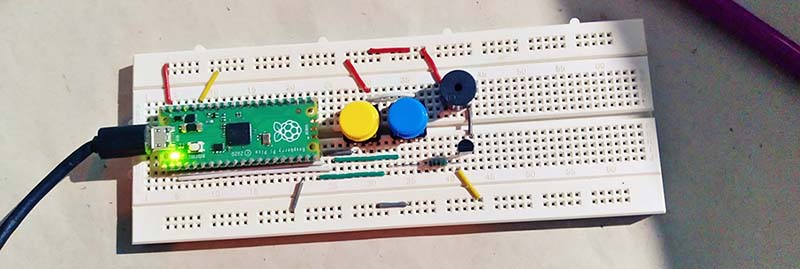
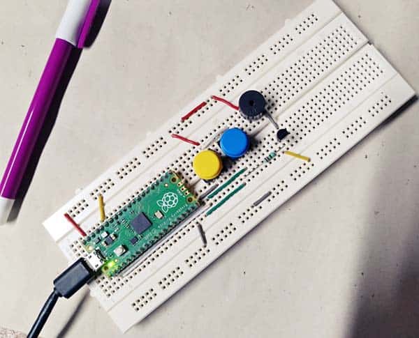
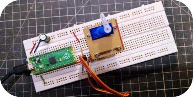
The below schematic uses two pushbutton inputs (GP0 and GP1) to control two outputs independently. The first output (GP25) is the onboard LED and the second output (GP15) is an active piezo buzzer. A simple piezo buzzer driver is also designed with the help of a very common NPN transistor – the S9013 (https://www.openimpulse.com/blog/wp-content/uploads/wpsc/downloadables/S9013-NPN-Transistor-TO-92-Datasheet.pdf).
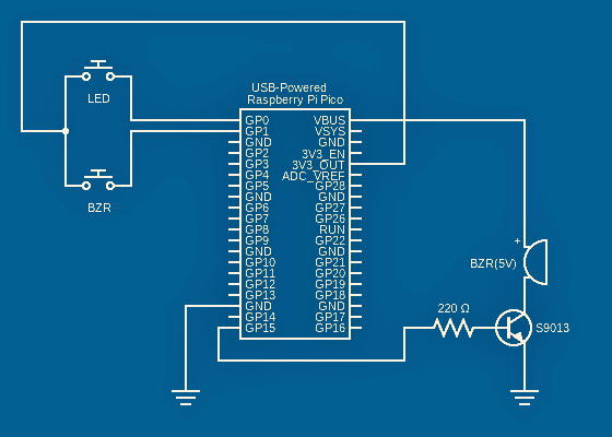
Alike the hardware, the software for this experiment/project is also very simple and straightforward. You can get it from below.
import machine

#Setup Digital Output x2
LED1 = machine.Pin(25,machine.Pin.OUT)
BUZ1 = machine.Pin(15,machine.Pin.OUT)

#Setup Digital Input x2
ButtonA  = machine.Pin(0, machine.Pin.IN,
                       machine.Pin.PULL_DOWN)
ButtonB  = machine.Pin(1,machine.Pin.IN,
                       machine.Pin.PULL_DOWN)

#Initialise the outputs as OFF
LEDState1 = False
BUZState1 = False

def ButtonAIRQHandler(pin):
    global LEDState1
    if pin == ButtonA:
        if LEDState1 == True:
            LEDState1 = False
        else:
            LEDState1 = True

def ButtonBIRQHandler(pin):
      global BUZState1
      if pin == ButtonB:
        if BUZState1 == True:
            BUZState1 = False
        else:
            BUZState1 = True

#Setup the IRQ and hook it to the handler
ButtonA.irq(trigger = machine.Pin.IRQ_RISING,
            handler =  ButtonAIRQHandler)
ButtonB.irq(trigger = machine.Pin.IRQ_RISING,
            handler =  ButtonBIRQHandler)

#Now loop and switch each ouput with its state
while True:
    LED1.value(LEDState1)
    BUZ1.value(BUZState1)
The button IRQ Handlers toggle the variables used to switch the outputs. They check which pin induced the IRQ, so the first button (GP0) controls the onboard LED (GP25) and the second button (GP1) controls the breadboard Buzzer (GP15). That’s it!
If you are new to the realm of Rpi Pico, refer to this primer at first https://www.codrey.com/raspberry-pi/raspberry-pi-pico-quick-start/
I know, the onboard LED doesn’t make much sense in a real-world application, however, you can change the sample code so that you’ll get two independent inputs and outputs for sensors and actuators. In a future post, I will take new steps to show you a selection of sensors, actuators, displays, and some other things that you can connect with RPi Pico. Be enthusiastic!
Bouncing & Debouncing?
When testing your prototype, you may find some strange things, but don’t panic!
Let me get to that directly. When a GPIO pin of the microcontroller is set as an input, it has no defined voltage levels. For us to be able to reliably detect whether the input is HIGH or LOW we need to tie it so that it is always connected and either reads HIGH or LOW. A “pulldown” connects the GPIO pin to GND through a comparatively high-value resistor so that when the switch is open there is a path to GND and so it will read LOW. When the switch is pressed there is a lower resistance path to 3.3V and thus the GPIO pin will read HIGH.
As you might already be noticed, in the above code example, one side of the pushbutton switch is wired to the RPi Pico’s GPIO and the other side is wired to the 3.3V rail. And, Pico’s internal pulldown resistor is used rather than adding an external resistor. Pretty nifty, but if you try it, you’ll probably find that sometimes the pushbutton functions erratically!
Yes, at times you found that it will actually happen several times in a very brief period for a pushbutton press, as the inside of the switch will act like a tiny spring. The problem you’re seeing is due to the switch contacts bouncing – hence switch bounces. But for a pushbutton, we’re probably only interested in seeing each button press as one event.
If that’s not clear enough, okay, just assume that you’re using an interrupt to increment a counter when the state changes on the GPIO. If your input is not properly debounced with either hardware or software, then a single button press might result in the counter incrementing several times when you’re expecting only a single increment. Even if you look just for “rising”, you’ll still get some bogus calls, as there’re both rising and falling edges when the switch bounces. Got it?
I will not elaborate on key bouncing/debouncing this time due to space constraints. Luckily, there’re several hardware/software-based solutions for switch bounce. You may go to this excellent report which has both hardware and software solutions https://my.eng.utah.edu/~cs5780/debouncing.pdf
In Closing…
So, we talked about the first steps of handling RPi Pico interrupts (more to come).
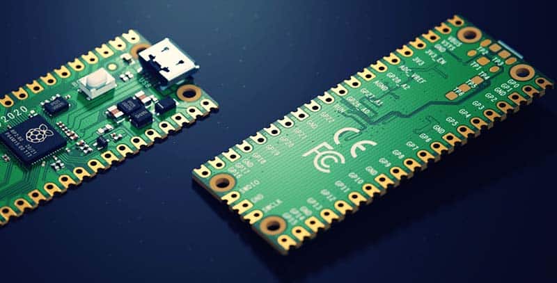
The Raspberry Pi Pico is indeed an awesome microcontroller capable of running codes to control physical hardware. It’s also pretty small with a form factor that’s not so different from certain Arduino boards. Moreover, since it can run MicroPython, it’s a budgetary microcontroller worthy for teaching aspects of text coding with kids.
As always, be sure to check out the RP2040 datasheet (https://datasheets.raspberrypi.org/rp2040/rp2040-datasheet.pdf) for in-depth learning…
Happy experimenting with the Raspberry Pi Pico
Nice and interesting article.
Well written
Thanks Shashi 💛