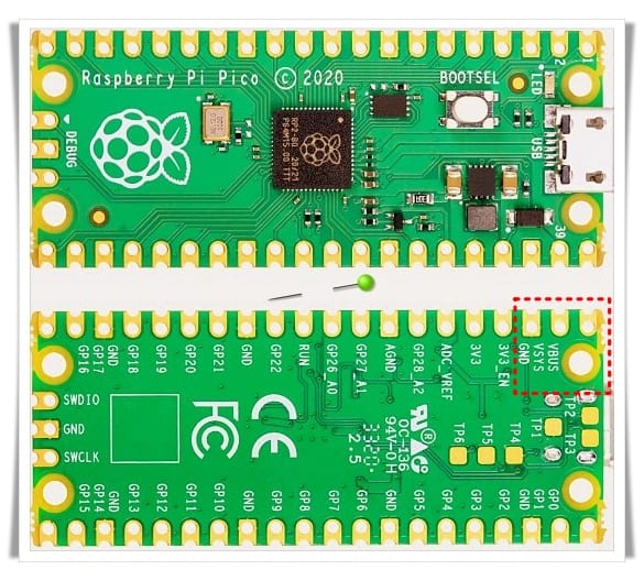
A couple of months after its release, ultimately, I got a hand on the Raspberry Pi Pico, and posted a few hobby projects here. The RPi Pico is a microcontroller board centered on the RP2040 which’s in fact a microcontroller chip designed by Raspberry Pi that features a dual-core Arm Cortex-M0+ processor with 264KB internal RAM and support for up to 16MB of off-chip Flash (https://datasheets.raspberrypi.org/rp2040/rp2040-datasheet.pdf).
Looking for a new Rpi Pico project idea? This tutorial is a simple guide on building a fancy light stick with Raspberry Pi Pico!
Before anything else, let me say this is a portable electronics project. This simply means the design is proposed to be put inside a translucent homemade or 3D printed shell with or without a built-in battery pack. If you opt for the non-battery version, simply use an external USB power supply as the power source.
Since the RPi Pico power supply option is also user-friendly, you can power your RPi Pico from 5V through micro-USB but it also accepts voltages from 1.8V up to 5.5V using an RT6150 based dc-dc buck-boost converter on its VSYS pin. This also allows the use of a rechargeable lithium battery or just a set of two (or three) NiMH batteries.
The below figure from the datasheet (https://datasheets.raspberrypi.org/pico/pico-datasheet.pdf) shows the options to connect several power sources.
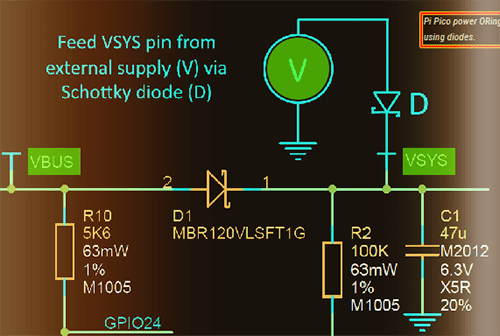
Right now, keep it in mind for consideration that the simplest way is to plug in the micro-USB, which will power VSYS (and therefore the system) from the USB 5V (VBUS), so VSYS becomes VBUS minus the Schottky diode (D1) drop. If the USB port is the only power source, VSYS and VBUS can be safely shorted together to eliminate the Schottky diode drop to improve efficiency and reduce ripple on VSYS. If the USB port is not going to be used, it is safe to connect VSYS to your preferred power source (V) preferably through a Schottky diode (D).
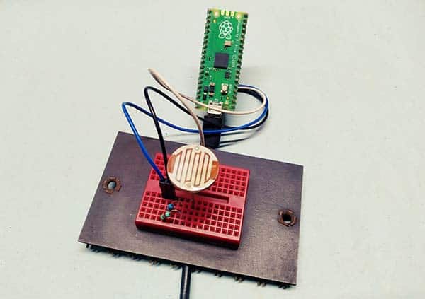
Back to the main theme, apart from the RPi Pico board, a WS2812-8 addressable RGB LED (also known as NeoPixel) stick is all that you needed to follow this project. Below you will see the basic hardware setup diagram.
![]()
Now create a new script in Thonny and paste into the following code.
import array, time
from machine import Pin
import rp2

#  Number of WS2812 LEDs
NUM_LEDS = 8
PIN_NUM = 22
brightness = 0.2

@rp2.asm_pio(sideset_init=rp2.PIO.OUT_LOW, out_shiftdir=rp2.PIO.SHIFT_LEFT, autopull=True, pull_thresh=24)
def ws2812():
    T1 = 2
    T2 = 5
    T3 = 3
    wrap_target()
    label("bitloop")
    out(x, 1)               .side(0)    [T3 - 1]
    jmp(not_x, "do_zero")   .side(1)    [T1 - 1]
    jmp("bitloop")          .side(1)    [T2 - 1]
    label("do_zero")
    nop()                   .side(0)    [T2 - 1]
    wrap()


# Create the StateMachine with the WS2812 program, outputting on pin
sm = rp2.StateMachine(0, ws2812, freq=8_000_000, sideset_base=Pin(PIN_NUM))

# Start the StateMachine - It will wait for data on its FIFO.
sm.active(1)

# Display a pattern on the LEDs via an array of LED RGB values
ar = array.array("I", [0 for _ in range(NUM_LEDS)])

#####################################################
def pixels_show():
    dimmer_ar = array.array("I", [0 for _ in range(NUM_LEDS)])
    for i,c in enumerate(ar):
        r = int(((c >> 8) & 0xFF) * brightness)
        g = int(((c >> 16) & 0xFF) * brightness)
        b = int((c & 0xFF) * brightness)
        dimmer_ar[i] = (g<<16) + (r<<8) + b
    sm.put(dimmer_ar, 8)
    time.sleep_ms(10)

def pixels_set(i, color):
    ar[i] = (color[1]<<16) + (color[0]<<8) + color[2]

def pixels_fill(color):
    for i in range(len(ar)):
        pixels_set(i, color)

def color_chase(color, wait):
    for i in range(NUM_LEDS):
        pixels_set(i, color)
        time.sleep(wait)
        pixels_show()
    time.sleep(0.2)

def wheel(pos):
    # Input a value 0 to 255 to get a colour value
    # The colour transitions loop R-G-B
    if pos < 0 or pos > 255:
        return (0, 0, 0)
    if pos < 85:
        return (255 - pos * 3, pos * 3, 0)
    if pos < 170:
        pos -= 85
        return (0, 255 - pos * 3, pos * 3)
    pos -= 170
    return (pos * 3, 0, 255 - pos * 3)


def rainbow_cycle(wait):
    for j in range(255):
        for i in range(NUM_LEDS):
            rc_index = (i * 256 // NUM_LEDS) + j
            pixels_set(i, wheel(rc_index & 255))
        pixels_show()
        time.sleep(wait)

BLACK = (0, 0, 0)
RED = (255, 0, 0)
YELLOW = (255, 150, 0)
GREEN = (0, 255, 0)
CYAN = (0, 255, 255)
BLUE = (0, 0, 255)
PURPLE = (180, 0, 255)
WHITE = (255, 255, 255)
COLORS = (BLACK, RED, YELLOW, GREEN, CYAN, BLUE, PURPLE, WHITE)

print("fills")
for color in COLORS:
    pixels_fill(color)
    pixels_show()
    time.sleep(0.2)

print("chases")
for color in COLORS:
    color_chase(color, 0.01)

print("rainbow")
rainbow_cycle(0)
If you haven’t already set up Thonny for programming your RPi Pico, do it first by going back to the previous RPi Pico articles published here. And then, make any changes you find necessary and run the final script. Your LEDs should render a few colorful patterns. Hope you get it right!

If you see the error message “no module named array”, try the latest firmware for RPi Pico (https://micropython.org/resources/firmware/rp2-pico-20210806-unstable-v1.16-160-ga3675294a.uf2). Also, go through this thread to get some quick hints https://www.raspberrypi.org/forums/viewtopic.php?t=303233
By this point, there are a few other important arguments to be aware of:
- NUM_LEDs is the number of LEDs in your WS2812 LED stick
- The DI (data input) pin is the control pin for the WS2812-8 LED stick. Likewise, DO (data output) pin on the same LED stick allows you to daisy-chain more WS2812-8 LED sticks, not tried in this project though
- PIN_NUM is the RPi GPIO pin for the data input of the WS2812 LED stick
Not to mention that but RPi Pico is a 3.3V microcontroller. So, there might be a communications mismatch when one of its data pins tries to talk to the NeoPixel’s data input, and results in a miscellany of odd behaviors, including incorrect colors, flickering, dimness, and seemingly dead pixels. A “logic level converter” is a cheerful solution to this problem as it listens to the 3.3V microcontroller data, translates it to a 5V-logic compatible message, and passes that along to the 5V NeoPixel

Most of the time the WS2822-8 LED stick will work without a logic level converter, and if that does not work, add one logic level translator to your light stick circuitry. Below is a bidirectional single-channel logic level converter circuit that seems to be suitable for this purpose. If you do not want to buy a prewired module, do it yourself with a 2N700x or BS170 MOSFET!
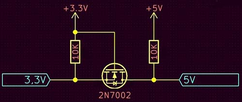
This is a very simple and extremely useful bit of electronics. When the low side (RPi Pico) outputs a ‘HIGH’ (3V3) the MOSFET is off. So, the high side (WS2812) pullup is active and pulls the high side to 5V. And, when the low side outputs a ‘LOW’ (0V) the MOSFET is on. The MOSFET then conducts to pull down the high side. How is it?
![]()
Ultimately, I prepared this entry-level article to respond to a couple of followers on Facebook who asked me how I got Pixel LEDs to work with Raspberry Pi Pico since they couldn’t. That was just after I posted a random lab snap on my Facebook page. In not much time I’d managed to wire up the entire setup, and I had a thing that worked.
![]()
Postscript
Here’s another code for the same RPi Pico Light Stick setup. As before, this code is also pretty simple and flexible. Enjoy!
import array, time
from machine import Pin
import rp2

#
############################################
# RP2040 PIO and Pin Configuration
############################################
#
# WS2812 LED Stick Configuration
led_count = 8 # Total NeoPixels
PIN_NUM = 22 # NeoPixel DI Pin
brightness = 0.2 # 0.1 = darker, 1.0 = brightest

@rp2.asm_pio(sideset_init=rp2.PIO.OUT_LOW, out_shiftdir=rp2.PIO.SHIFT_LEFT,
             autopull=True, pull_thresh=24) # PIO configuration

# define WS2812 parameters
def ws2812():
    T1 = 2
    T2 = 5
    T3 = 3
    wrap_target()
    label("bitloop")
    out(x, 1)               .side(0)    [T3 - 1]
    jmp(not_x, "do_zero")   .side(1)    [T1 - 1]
    jmp("bitloop")          .side(1)    [T2 - 1]
    label("do_zero")
    nop()                   .side(0)    [T2 - 1]
    wrap()


# Create the StateMachine with the ws2812 program, outputting on pre-defined pin
# @ 8MHz frequency
state_mach = rp2.StateMachine(0, ws2812, freq=8_000_000, sideset_base=Pin(PIN_NUM))

# Activate the state machine
state_mach.active(1)

# Range of LEDs stored in an array
pixel_array = array.array("I", [0 for _ in range(led_count)])
#
############################################
# Functions for RGB Color
############################################
#
def update_pix(brightness_input=brightness): # Dimming colors and updating state machine (state_mach)
    dimmer_array = array.array("I", [0 for _ in range(led_count)])
    for ii,cc in enumerate(pixel_array):
        r = int(((cc >> 8) & 0xFF) * brightness_input) # 8-bit Red dimmed to brightness
        g = int(((cc >> 16) & 0xFF) * brightness_input) # 8-bit Green dimmed to brightness
        b = int((cc & 0xFF) * brightness_input) # 8-bit Blue dimmed to brightness
        dimmer_array[ii] = (g<<16) + (r<<8) + b # 24-bit colour dimmed to brightness
    state_mach.put(dimmer_array, 8) # Update the state machine with new colors
    time.sleep_ms(10)

def set_24bit(ii, color): # set colors to 24-bit format inside pixel_array
    pixel_array[ii] = (color[1]<<16) + (color[0]<<8) + color[2] # Set 24-bit color

#
############################################
# Main Loops and Calls
############################################
#
color = (255,0,0) # Looping color
blank = (125,125,0) # Color for other pixels: Now Dim Yellow
cycles = 12 # Number of times to cycle 360-degrees
for ii in range(int(cycles*len(pixel_array))+1):
    for jj in range(len(pixel_array)):
        if jj==int(ii%led_count): # In case we go over number of pixels in array
            set_24bit(jj,color) # Colour and loop a single pixel
        else:
            set_24bit(jj,blank) # Turn others OFF
    update_pix() # Update pixel colors
    time.sleep(0.05) # Halt 50ms
Sources of Inspiration: https://core-electronics.com.au/, https://realpython.com/, https://makersportal.com/, https://www.settorezero.com/wordpress/