Some time ago my neighbor asked me to design a better light sensor module. In fact, he already has a few small light sensor modules to automatically control the lights in his barn. Those cheap light sensor modules made with standard photoresistors and comparator chips still work well.
So, after some thought, I decided to make a completely different light sensor module for him. Let us first look at its schematic.
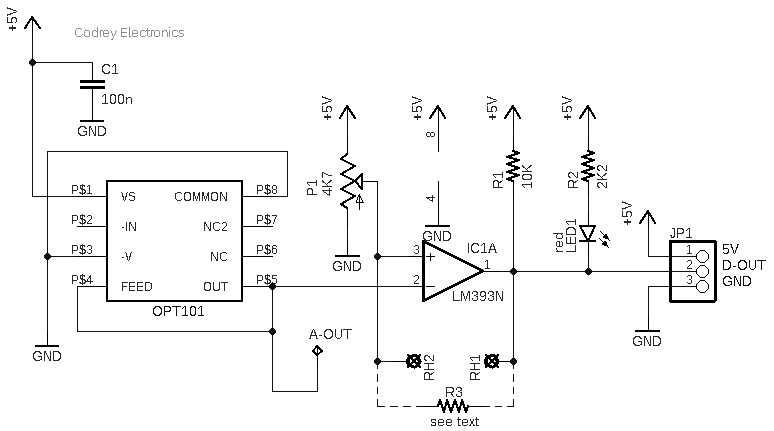
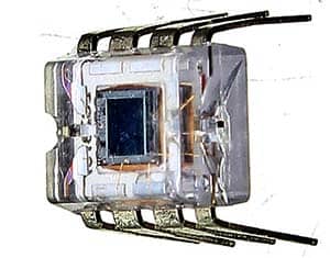
As seen in the above drawing, the design does not use a standard photoresistor or phototransistor, but instead employs a dedicated analog light sensor OPT101 as its core!
Analog Light Sensor OPT101
The OPT101 is a monolithic photodiode with an on-chip transimpedance amplifier. The ingenious integration of a photodiode and a transimpedance amplifier on a single chip eliminates the problems commonly encountered in discrete designs. The OPT101 operates from 2.7V to 36V supplies and quiescent current is only 120μA. Its output voltage increases linearly with light intensity (https://www.ti.com/lit/ds/symlink/opt101.pdf).
Originally, I considered using a discrete photodiode and a transimpedance amplifier circuitry to formulate a way to detect/measure the intensity of the ambient light. However, the integrated OPT101 design provides a pretty reliable operation under a number of light conditions. So, I simply picked out the integrated analog light sensor for my new experiment.
Voltage Comparator LM393
The LM393 (https://www.onsemi.com/pdf/datasheet/lm393-d.pdf) voltage comparator simply processes analog output from the OPT101 light sensor to render an active digital output. The TTL output of this circuit is normally in logic-high (H) state which goes to logic-low (L) when the light level sensed by OPT101 crosses a certain threshold set by the trimpot. This configuration obviously allows this light sensor design to be used as a standalone digital switch or as a compact sensor head for driving a secondary on/off switch control circuitry.
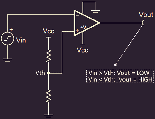
The comparator is used to differentiate between two different signal levels. The comparator will compare the input signal (Vin) to the threshold voltage (Vth). The comparator input signal is applied to the inverting (-) input, so the output will have an inverted polarity. When the Vin > Vth the output (Vout) will drive to the negative supply (GND/LOW). Likewise, when Vin < Vth the output (Vout) will drive to the positive supply (VCC/HIGH). This simple method can be used to determine if a real-world signal such as light level is above some critical value.
Comparator & Hysteresis
However, a comparator that does not use hysteresis has a serious shortcoming – the noise on the input signal can cause the input to transition above and below the threshold causing an erratic output. In other words, noise or signal variation will cause multiple transitions near threshold.
Hysteresis, however, sets two thresholds (upper and lower) to eliminate the multiple transitions caused by noise. In the below figure, the new resistor (Rhyst) sets the hysteresis level.
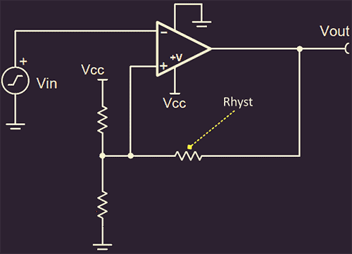
Consequently, I included solder pads for an extra resistor in my design to impart some hysteresis to the comparator. This means, once the light sensor output reaches the set threshold, the comparator output will change, but will also modify the threshold voltage. So, in order for the comparator output to switch again, the light sensor must then raise a considerable amount of voltage to reach the threshold again, and this gives a good leeway to cope with the potential perturbations.
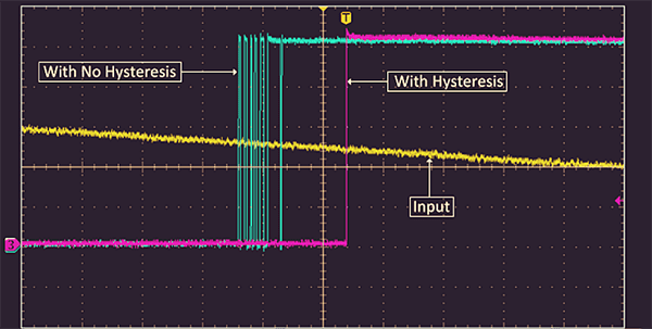
Below scope, capture depicts the output for a comparator with and without hysteresis with a noisy input triangle waveform applied. Look, the circuit without hysteresis has multiple transitions at the threshold voltage whereas the circuit with hysteresis has a single transition at the threshold (Thanks Texas Instruments).
Quick Evaluation
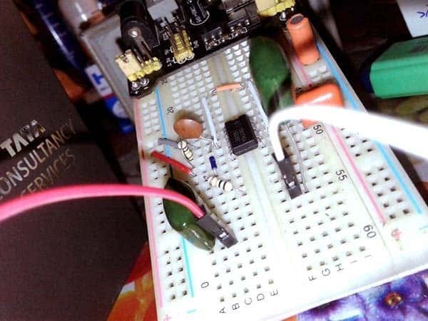
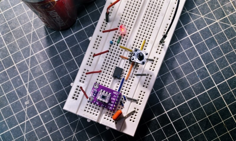
In the usual manner, I built my first prototype on a breadboard (see below).
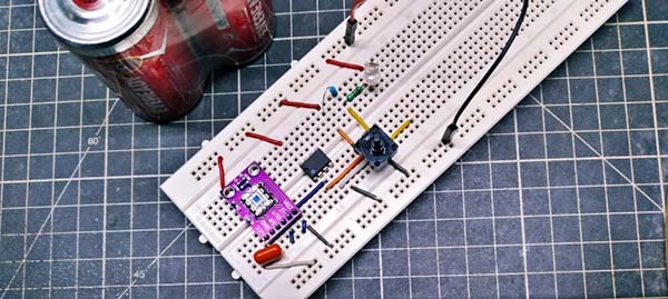
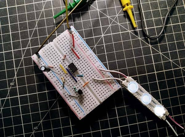
I used my white LED desk lamp as a light source with a digital lux meter to set and check the thresholds.
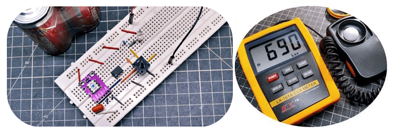
And, tested the quick prototype successfully!
As an aside, I ended up using a 10KΩ “hysteresis” resistor (after taking the photos above). It works fine enough, but I’ll probably change it later after some field tests. As noticed, my OPT101 delivers an analog voltage output in 0V to circa 4V range at 5VDC operation.
The degree of hysteresis designed into a comparator circuit is determined by the difference between the high and low thresholds. A small difference is less tolerant of noise. However, a larger difference has a more muted response, which must be considered in its effects on a circuit’s behavior.
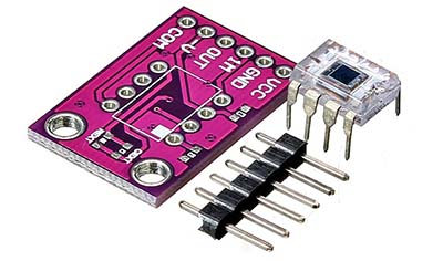
Breakout Board CJMCU-101
Before I forget, what you can see on my breadboard is the OPT101 sensor that’s mounted on a CJMCU-101 breakout board (https://www.elecrow.com/cjmcu-101-opt101-analog-light-sensor-light-intensity-module-monolithic-photodiode.html).
Push Further
Luckily both OPT101 light sensor and LM393 comparator features a wide supply voltage range. Therefore, you can build TTL and CMOS logic compatible light sensor modules easily. Further, the responsivity of the OPT101 sensor can be modified using two simple passive components – only one resistor and one capacitor are required. Read page 9 of this OPT101 datasheet to learn more about responsivity tweaks https://people.ece.cornell.edu/land/courses/ece5030/labs/s2014/opt101.pdf
That’s all for now. Also, if anything isn’t clear let me know in the comments. I’ll try to amend this write-up with anything I may have missed!