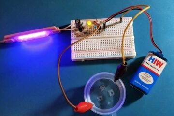
In this article you can see an ultra simple circuit of a lightweight, truly portable, and compact anti-snatch alarm. This trembler alarm is battery operated and features a tone generator capable of drawing quick attention of nearby people. It is cheap, simple to use, and does not need any additional wiring except an obtrusive security cable.
Typical Applications
Anti-snatch alarm is a common security enhancement device broadly used for protection of valuable objects in museums and exhibition halls as it can quickly detect “snatch and grab” attempts. In addition it can also be used to add an extra layer of security to a traveler’s baggage, certain portable electronics devices, etc.
Circuit Diagram
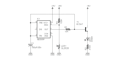
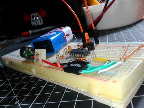
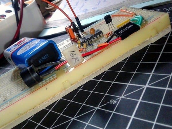
In the above circuit diagram, a low-frequency tone generator (~170Hz) is formed by first two gates (IC1A & IC1B) of the hex inverter chip MC14069UB (IC1). Output of the tone generator drives a standard 16Ω piezo-speaker (PZS) – not a piezo buzzer – through the third gate (IC1C) of the inverter chip, while the associated S8050 transistor (T1) works as the piezo-speaker driver. Here, components R3 and C2 are the main elements that set the frequency of the tone generator. Final gate (IC1F) of IC1 gates the tone generator oscillator, i.e. enables it by a low-level output (L) and disables it by a high-level (H) output. The security loop (wire/cable loop) grounds the input of the final gate and thus disables the alarm function in idle state. One 6F22 9V transistor radio battery powers the entire circuit through a small power on/off slide switch (S1).
Component List
- R1: 100K ¼ w
- R2: 470K ¼ w
- R3: 270K ¼ w
- R4: 1K ¼ w (see notes)
- C1: 100uF/16v
- C2: 10nF/50v
- D1: 1N4148
- T1: S8050 or SS8050
- IC1: MC14069UB or CD4069UB
- PZS: 16Ω Piezo-Speaker
- S1: SPDT Slide Switch
- JP1: Socket for Security Loop (: 2-pin male-header)
- BAT: 6F22 9V Battery
Construction Notes
The circuit can be assembled on a small piece of perforated circuit board (shaped like a ring) preferably with one good quality socket for the hex inverter chip (IC1).

Components layout is not very critical, however, try to keep all interconnections as short as possible. Inputs of the two unused gates (IC1D & IC1E) of the hex inverter chip must be tied to ground rail (0V) but leave their outputs stay remain unconnected. The circuit draws negligible current in idle state but it shoots up to or above 100mA in active state, so, a tradeoff is needed to be made in the selection of the 1K resistor (R4). You can start your own tinkering with standard resistor values from 1K to 10K to get a rich tone output while keeping the overall current consumption temperate.
After successful construction, put the whole assembly inside a suitable, attractive, and easy to carry enclosure fitted with a socket for the security cable. Also remember to mount the power switch in a hidden portion of the proposed enclosure. The security cable is nothing but a short-piece of common single-core sheathed low-voltage flexible wire which bridges the connection points of the security cable socket (J1). If you prefers an ‘invisible’ security loop, then go for a thin magnet wire (the so called winding wire – enameled copper wire) loop instead of the flexible wire loop.
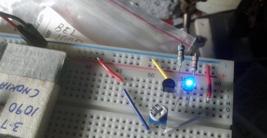
See snaps of my breadboard version:
Usage Hints & Tips
The anti-snatch alarm should be tied to the object to be protected using a suitable snap hook or other method of your choice. To set the alarm, insert the security loop into its socket and flick the power on/off switch. Do ensure that the alarm box loops the object perfectly through its security cable. For example, when going out, attach the snap hook to the strap/handle of your handbag/briefcase and hold the security loop or slip it around your wrist. If your bag is snatched while you are holding on to it, the security loop will be pulled out of its socket, and the alarm siren is activated instantly to startle the snatcher. The alarm signal also attracts others immediate attention and alert for help!
The 9V Battery Facts
Everyday we can see electronics hobby circuits powered by 9V transistor radio style batteries. Actually the general purpose 9V battery is not a good companion for many of such circuits as the battery is designed for very low current draw. Cheap version of such an “IEC- 6F22 9V” battery usually has a rating of 500mA @ 9V but in principle it’s never meant to be discharged at 500 mA. The battery capacity will be better with lower drain currents, to say 15mA (however, it’s evident that some heavy-duty 9 volt batteries are better than others at this high current). To estimate the battery life, just divide the battery capacity by the actual load current to get the hours of life. The circuit designer must know what to expect when the 9V battery is used under a high-current draw circumstance.
Following is the typical response curve of a common Eveready Silver 9V “carbon-zinc” battery (9.0V/400mAh) when discharged through a 180Ω dc load (thanks to www.energizer.eu).
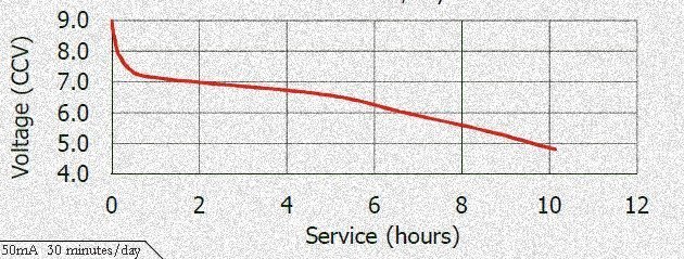
Our anti-snatch alarm draws current close to 5mA in idle state at 9V, therefore the continues current drain (if armed) will be the same 5mA (varies according to the temperature). Although even this lower number won’t make a favorable impression, we’ll get a reasonable relief only because of the short run time of the alarm system!