Afraid of snakes? Don’t worry, here is a portable electronic snake repeller solution to keep all poisonous snakes out of your surroundings. All you need is to simply put the device on the bare floor/soil to scare away many kinds of snakes, quickly and safely. Design of the little device is based on the proven fact that snakes will flee if get an opportunity to do so. As the device emits a strong pulsing vibration into the bare floor/soil, snakes perceive the vibration as a source of danger and moves away to avoid encounter.
Circuit Diagram
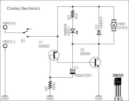
Function of the circuit is very simple – to briefly turn on a vibrator at regular intervals. Just to simplify, T1 is responsible for the on/off pulses, and T2 works as the vibrator driver (actually a 2-transistor complementary relaxation oscillator). R1 and C1 in the main determines the drive pattern of the vibration motor (VBM). LED1 is a status indicator while D1 is for circuit protection against inductive kick-back.
Parts List
R: 100K ¼ w
R2: 1K2 ¼ w
C1: 100uF/25v
T1: S8550
T2: S8050
LED1: 5mm (Amber)
D1: 1N4007
VBM: 3-5V Vibration Motor / Pancake Motor (see text)
S1: SPST (or SPDT) switch
BAT: 6F22 9V Battery (see text)
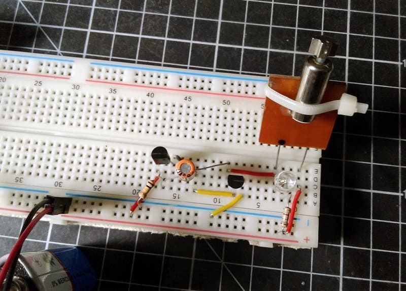
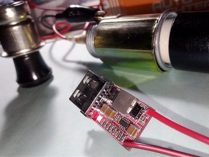
The vibration motor used in my prototype has a size of 6.7×14.5mm ( I got it from eBay). Do not use a home-made vibration motor (built with cheap toy car/disc drive motor + eccentric load) as an alternative here. Given below is the random snap of my experiment on breadboard. Quick video link – https://www.youtube.com/watch?v=yWTViJYy3aw
Construction Clues
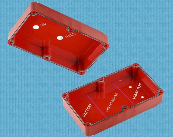
The actual construction should not present problems as only through-hole components are involved and a single-side circuit board. You can use a medium-size prototype enclosure for this snake repeller. The enclosure must have enough space to hold the battery, finished circuit board, vibrator, switch, and the indicator lamp. It’s good to attach the vibrator to the bottom plate of the enclosure by a small cable tie or motor clamp (see the enclosure layout suggestion given below).
For real world applications, note that a firm physical contact of the device with bare floor/soil will greatly affect the effectiveness of the device. The more good the impact, the better the device will function!
Lab Note
Although the circuit design is optimized for 9V battery operation, it’s possible to run it from a 6V (1.5×4) standard battery pack/4.8V (1.2×4) Ni-MH battery pack, or 1S Li-Ion (3.7V) battery. With a lower operating voltage, however, the overall impact will be reduced slightly. Observed peak current consumption of my prototype is about 35mA at 9V. Actually, the current intake resembles a funny waving pattern, hence there’s not so much loading effect on the battery.
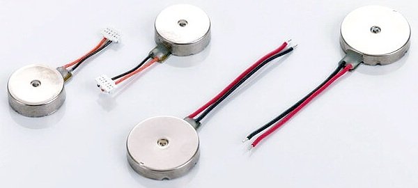
You can try another compact motor – the so called ‘Pancake Motor’ – in lieu of the big vibration motor (pager motor) used here. Pancake motors are very convenient to use because they have no external moving parts, and just can be affixed in place with the pre-attached adhesive sticker on the back of it. In principle, pancake vibration motors use the same operating principle as eccentric rotating mass motors (pager motors), however, their eccentric mass is kept in their small circular body having diameter ranges from Ø7mm to Ø14mm. This low-profile construction technique makes them suitable for space-restricted applications.
Surprisingly it’s noticed that this device repels lizards too. If you want to avoid exposure to poisons or toxins that are usually associated with traditional pest controls, just hang this device on the wall for effective lizard control.
& Finally:
Since the vibrator part (output load) determines the impedance of the final stage which limits the amount of drive available for feedback, a little tinkering on the capacitor and/or resistor values might be needed if your vibrator is different. You can also try the inclusion of a current-limiting resistor between the transistors to make the circuit more safe.
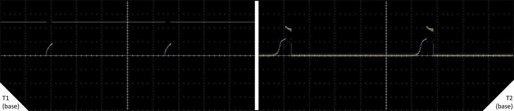
Addendum
Random screenshots of oscillograms from my USB oscilloscope follows. See the left (base of T1) & right (base of T2) waveforms; only for basic reference.

Dear Hareendran
Many thanks for the article , for a school project we would appreciate your kind advice in fine tuning the prototype . Kindly advise your e mail ID
If you have any questions about this article, please drop me a note in the comment. I will try to help. Thank you for your keen interest in my little circuit!
Can we fix this in our shoes??it will be more helpfull for travellers
Can I get a video tutorial of construction of this circuit/device.
is it working in real time.
prasanna: Sorry I didn’t get you right.! What you meant by “real time”? Hope you elaborate…