Here’s a project for fun – Magnetic LED Throwies!
LED Throwies were invented in 2006 by the Grafitti Research Lab in New York City to use as non-destructive graffiti. Build one (or several) yourself right now!
This project can be extremely fun as long as you proceed with keen interest and properly build your cheery gleam dots. Luckily, you can make fantastic LED Throwies in just a bit from simple components, and can stick them easily onto any ferromagnetic surface.
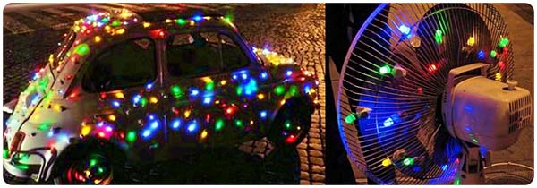
For example, put them on the metal blades of a pedestal fan, or consider your grandad’s car as a perfect target for tossing them. Also, check out real-world shots included here for your inspiration (borrowed from the web).
I plan to share a couple of amusive project ideas. Okay, let’s get started…

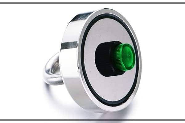
What you need to gather to make your Magnetic LED Throwie? Look, a magnetic LED Throwie basically consists of a small battery pack, one or more LEDs, and a rare-earth magnet merged together. So, first of all, you need to collect enough neodymium magnets (round magnets are better). Below you can see my collection of round neodymium magnets.
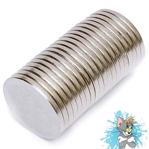
Note that neodymium magnets are incredibly powerful rare-earth magnets which makes them extremely hazardous to kids, pets, electronic devices, magnetic storage media, etc. Therefore, do not handle them carelessly!
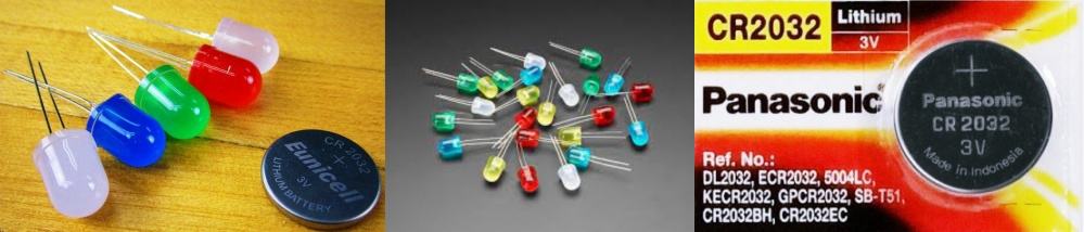
The next component is the light-emitting diode (LED). Luckily, you often have a mason jar full of used LEDs leftover from old projects that you can re-purpose. Else, get ready to buy a miscellany of common LEDs (10mm diffused LEDs are better).
Last key element is the coin-cell battery. The best pick here will be the CR2032 Lithium 3V Battery.
Okay, let’s dive in!
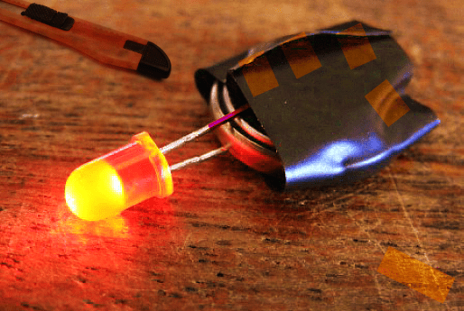
The simplest models are always-on glow-dots made with a lithium battery, a light-emitting diode, and a strong rare-earth magnet. Props to Graffiti Research Labs for the original idea!
To make it, you first need to place the lithium battery with the correct electrical polarity between the anode (A/+) and cathode (K/-) leads of the LED. Note that the positive terminal of the coin-cell has a larger contact surface than its negative terminal. So, don’t let the cathode lead of the LED accidentally touch the positive plate extending around the sides of the coin-cell because it will create a short circuit.
Next, attach the neodymium magnet to the battery and the LED. Finally, wrap the entire assembly in electrical insulating tape. You can also dip your final build in epoxy, silicon, or potting compound to make a weather-friendly LED Throwie.
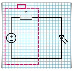
This simplest model does not have a series resistor (for current limiting) in between the battery and the lamp, and this often causes some confusion. Actually, there’s a series resistor, you just can’t see it though. Recall that all cells and batteries have some internal resistance, and that’s why a battery is usually modeled as an ideal constant voltage source with series resistance.
By measuring the no-load cell voltage and the loaded cell voltage we can measure the internal cell resistance.
For example, presume that the potential difference across a cell when it’s not connected to a load is 3.0V, and it falls to 2.4V when a load is connected to the cell, and the load current measured is 20mA.
Then using Ohm’s law, we can calculate the internal resistance as 3.0V-2.4V /0.02A = 30Ω.
Anyway, note that just because the trick works here with a coin-cell, it doesn’t mean it’s a good idea with other power sources. Beware, such an attempt will definitely destroy the LED.
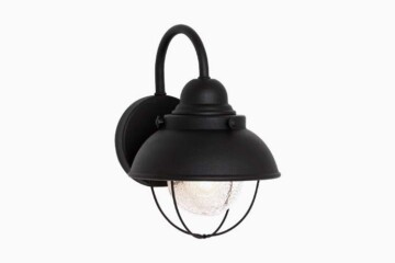
Coming back to the build ideas, first off make your basic model and then slip it inside a durable enclosure as shown in the below example. If so, it can survive bad weather, so it’s ideal for outdoor signaling and/or anything you can think of.
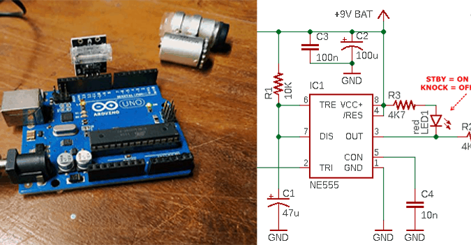
I agree that the commonly followed concept discussed above is not a pretty viable approach due to some inherent issues. Although adding a minuscule power switch will lengthen the lifetime of your LED Throwie since you can easily turn it on and off, my next plan is to show you the idea of an automatic version that glows only in the dark, not in the daylight. The scheme of this improvement is also elementary, but it calls for a few more components (see the schematic shown below).
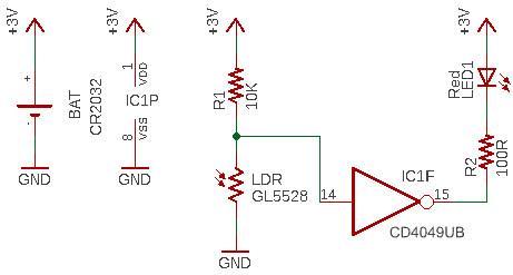
As you can see, this belittled circuit uses only one gate of the CMOS Hex Inverting Buffer CD4049UBE (IC1). That means five unused gates are still available for your expansion ideas!
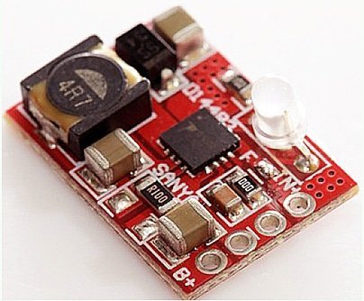
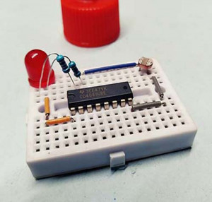
Now see a quick test snap of my mini breadboard prototype!
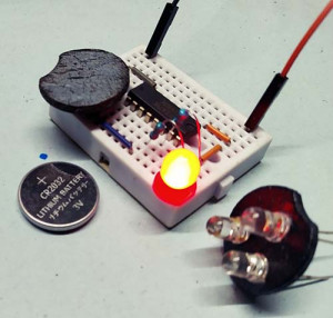
A magnetic LED Throwie is a quick way to add vibrant colors to any ferromagnetic surface in your surrounding region. Note that you can make a better “sensor-triggered” LED Throwie by using tiny chip parts (SMDs). I’ve already built my first prototype using a commonly available mini logic chip – 74VHC1G135.
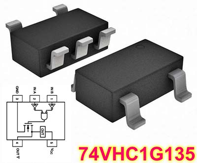
The 74VHC1G135 (https://www.farnell.com/datasheets/701896.pdf) is a 2-input NAND Schmitt trigger fabricated with silicon gate CMOS technology. Its internal circuit is composed of three stages, including an open-drain output which provides the capability to set the output switching level. So, stay tuned to see my upcoming Balloon LED Throwie project.
All that’s left at this time is to build, decorate, and toss your own Magnetic LED Throwies. Have fun!