A few months ago, I read about some strange issues with Raspberry Pi Pico’s ADC. According to those stories, Raspberry Pi has confirmed its investigation of reports of a design flaw in the ADC (analog to digital converter) on the Raspberry Pi Pico and other RP2040 microcontroller-based boards, which manifests itself as measurable spikes in DNL (differential non-linearity).
A while later, Raspberry Pi’s Alasdair Allan confirmed the investigation is still underway (https://github.com/raspberrypi/pico-feedback/issues/91).
You can read an analysis of the root cause of the problem on Mark Omo’s website (https://pico-adc.markomo.me/INL-DNL/#why-does-thednlspike).
Okay, I will set aside some time for updates on this later. In the meantime, let’s have a quick look at the ADC basics of Raspberry Pi Pico!
Raspberry Pi Pico & ADC Overview
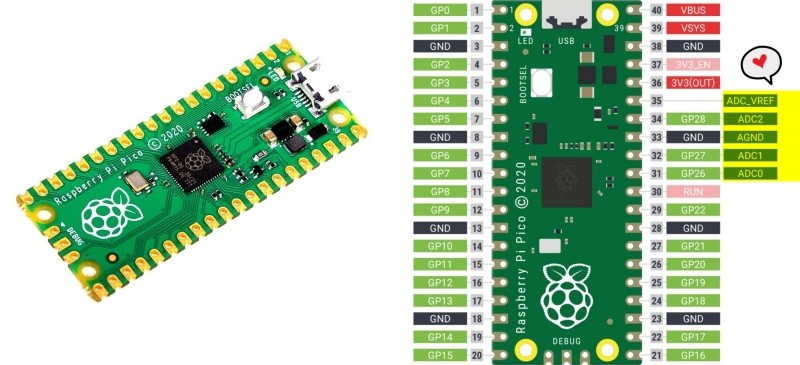
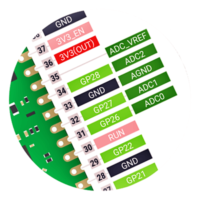
The Raspberry Pi Pico board features four externally accessible ADC pins. You can see them labelled as ADC0, ADC1, ADC2, and ADC_VREF (ADC3) in the pin notation chart. The internal chip temperature sensor is on ADC4.
In a simple manner;
- ADC0 = GP26/PIN 31
- ADC1 = GP27/PIN 32
- ADC2 = GP28/PIN 34
The ADC pins of Raspberry Pi Pico support 12-bits, which means, the value can go from 0 to 4095. However, since MicroPython code can scale the ADC values to a 16-bit range, the effective range is from 0 to 65535. Now note that the microcontroller works at 3.3V, so an ADC pin will return a value of 65535 when 3.3V is inputted to it or 0 when there’s a zero voltage input.
Raspberry Pi Pico & ADC Experiments
So, your Raspberry Pi Pico has dedicated ADC input pins that can handle analog signals. This means that instead of only reading the values of 1 and 0 (HIGH and LOW), it can read values in between. Now follow the wiring diagram below to setup your hardware for a quick ADC experiment!
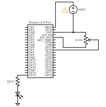
You can now use the below code to control the duty cycle for PWM on the LED. Once you’ve run it, turn the potentiometer’s knob to regulate the brightness of the LED.
from machine import Pin, PWM, ADC

pwm = PWM(Pin(15))
adc = ADC(Pin(26))

pwm.freq(1000)

while True:
  duty = adc.read_u16()
  pwm.duty_u16(duty)
Let’s recap, the Pico has a single 12-bit resolution, 4-channel ADC with a 3.3V internal reference, and available inputs on 0-3 (GP26-29). This means you can measure input voltages between 0V and 3.3V (maximum) at a resolution of 0.81mV although in MicroPython this is scaled to a 16-bit value from 0 to 65535.
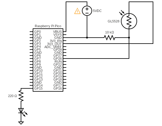
The next experiment needs a bit different hardware setup. Here, the brightness of the LED is controlled by the amount of light falls on an LDR. This is in fact a crude “automatic night lamp” idea centered on Raspberry Pi Pico. Now simply run the below code in Thonny as done in the previous experiment.
from machine import Pin, PWM, ADC

pwm = PWM(Pin(15))
adc = ADC(Pin(26))

pwm.freq(1000)

while True:
  duty = adc.read_u16()
  pwm.duty_u16(60000-duty)
This is the hardware setup diagram:
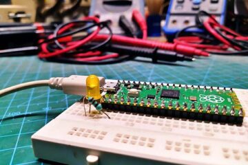
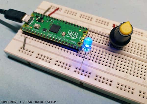
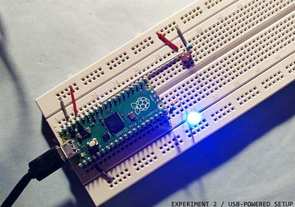
Below you’ll see a random snap of my quick experiment setup on a standard breadboard.
The third experiment is to read the temperature from the internal temperature sensor. This is the code I used for my quick tests:
import machine
import utime

sensor_temp = machine.ADC(4)
conversion_factor = 3.3 / (65535)

while True:
    reading = sensor_temp.read_u16() * conversion_factor
    temperature = 27 - (reading - 0.706)/0.001721
    print(temperature)
    utime.sleep(2)
If everything goes well, the Shell Window will start displaying the temperature value in °C.
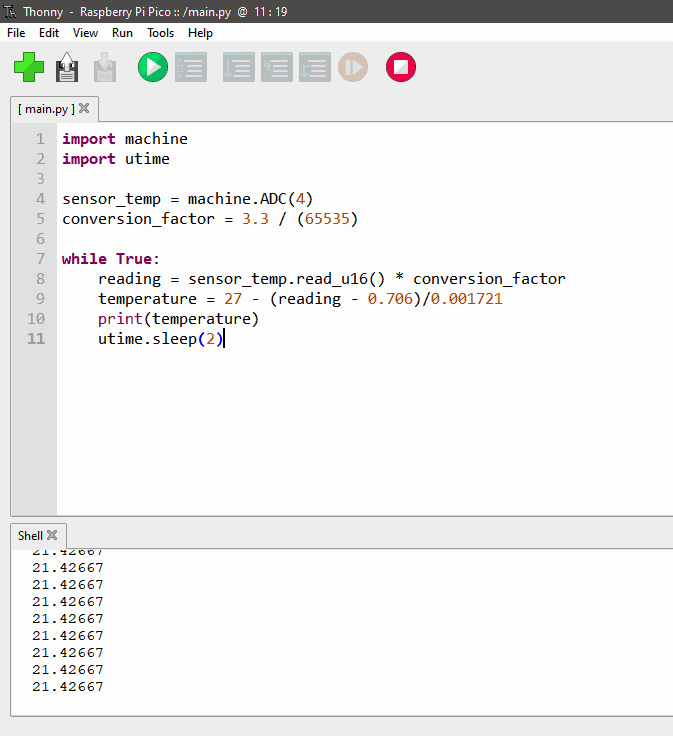
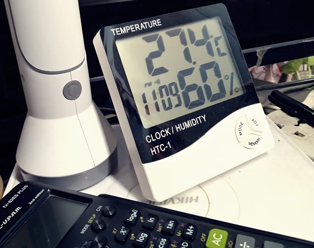
As you can see in the above screen snap, I’m getting somewhat sensible temperature readings. The room temperature is around 27°C.
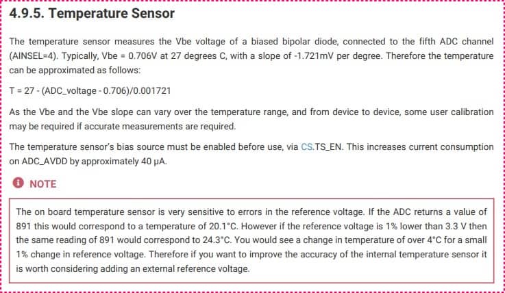
It’s worth recalling at this time that the calculated chip temperature depends on the actual Vref value being used in the calculation. The Raspberry Pico datasheet notifies us that the nominal Vref value will be slightly under the expected 3.3V.
The temporal end!
Thus, we went through some simple experiments and learned how to connect and read analog things and use their input to control digital outputs in MicroPython. The last example demonstrated reading the internal temperature sensor in a lucid way.
Further information about the Raspberry Pi Pico can be found in the datasheet (https://datasheets.raspberrypi.com/rp2040/rp2040-datasheet.pdf. )
Moreover, the examples provided here can be used as a basis for many different input/output scenarios with compatible analog sensors and breakout boards/modules.
I’m planning a new ADC project, but not yet telling what it will be. So, stay tuned…
Credits & References