Lately, I started thinking about a digital start/stop power switch box. Sure, I could buy one easily but where is the fun in that? In this post, you will find an outline of that small project, and some random notes I jotted down while developing the prototype. Okay, let’s get started!
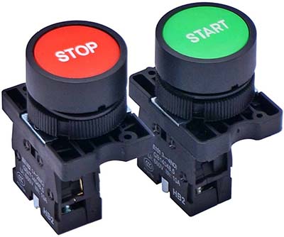
The start/stop switch box presented here is extremely easy and straightforward to operate and does not require expert intervention. The system includes a pair of momentary push buttons that enables a user to turn the connected equipment on or off. Because the buttons are “digital”, they can also be remotely controlled with low voltage cabling to start or stop the connected device. You can also try radio links to operate them if needed.
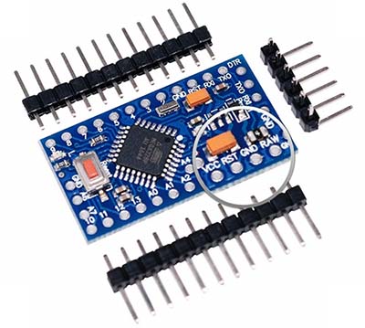
An Arduino Pro Mini (3.3V/8MHz) was deliberately chosen here because it’s a pretty compact microcontroller board and therefore demands very little space inside an enclosure. Besides the small size (and cost), the other benefit to using Pro Mini is that it needs much less power than an Arduino Uno.
The Arduino Pro Mini (3.3V/8MHz) can be powered with a regulated 3.3VDC supply on the VCC pin. There’s a voltage regulator on board so it can accept voltage up to 12VDC. If you’re supplying unregulated power to the board, be sure to connect to the “RAW” pin on not VCC. According to the Arduino Pro Mini spec, the RAW pin can take 3.35-12V (3.3V model).
The power supply input pins are as follows:
- RAW: Raw Voltage Input
- VCC: Regulated 3.3VDC Input
- GND: Ground/0V
Arduino Pro Mini 3.3V/8MHz Datasheet https://www.digikey.in/htmldatasheets/production/1732755/0/0/1/dev-11114.pdf
So, the HLK-5M05 SMPS module (https://5.imimg.com/data5/JI/JR/RP/SELLER-1833510/hlk-5m05-power-module.pdf) was chosen as the power source for this project. You can go for other options, no problem!
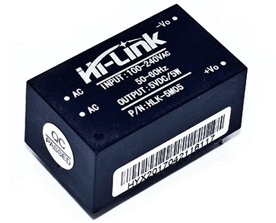
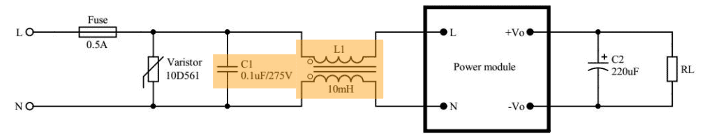
It’s highly recommended to run this module with two basic input protection components – a slow fuse (500mA/250VAC) and a varistor (10D561K). Further, a 100-220uF aluminum electrolytic filter capacitor can be connected at its output to reduce the output ripple. See the typical application circuit below (the shaded components are not so crucial in a hobby electronics design).
A relay is an electromagnetic (or electromechanical) switch that is used to switch a high voltage/current load often thru a low voltage control circuit. The relay isolates the low voltage section of the control circuit from the high voltage switch section.
Since a microcontroller is not able to drive a relay directly, it should not be connected to the GPIO pin of a microcontroller like Pro Mini – you should employ a suitable driver circuit in between (https://www.electroschematics.com/microcontroller-relay-interface-and-driver/).
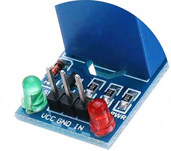
For this project, we will be using a prewired 5V relay module which makes the overall wiring, experimenting, and building of the project more comfortable. This is a relay module option you can consider – 5V (1 Channel) Relay Module (High-Level Trigger).
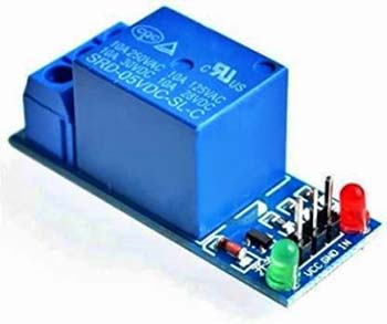
Note: You have to power the relay module by its intended operating voltage (5V). Then the 3.3V trigger signal from the Pro Mini may be sufficient for the proper operation of the module. Else, you may need to change the base resistor (mostly 1KΩ) of the NPN driver transistor in the relay module.
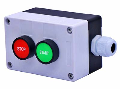
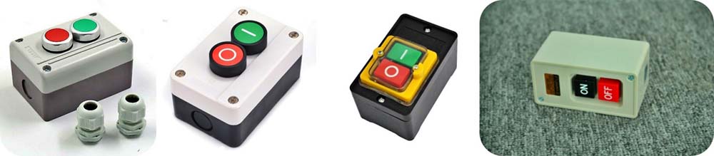
In addition to a nifty project enclosure (switch box), all you need now are two pushbutton switches (choose them as you like).
Here’s the Arduino Sketch. Simply upload this to your Pro Mini Start/Stop Switch setup.
int startButton = 2;
int stopButton = 3;
int relayDrive = 13;
//int relayDrive = 12;
int startStatus = 0;
int stopStatus = 0;

void setup() {
pinMode(relayDrive, OUTPUT);
pinMode(startButton, INPUT_PULLUP);
pinMode(stopButton, INPUT_PULLUP);
}

void loop() {
startStatus = digitalRead(startButton);
stopStatus = digitalRead(stopButton);
if (startStatus == LOW && stopStatus == HIGH)
{ digitalWrite(relayDrive, HIGH); }
if (startStatus == HIGH && stopStatus == LOW)
{digitalWrite (relayDrive, LOW); }
}
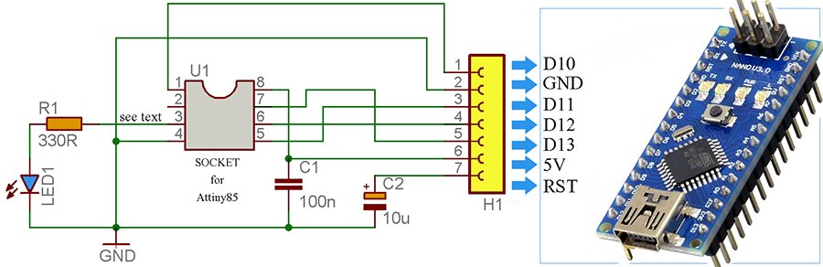
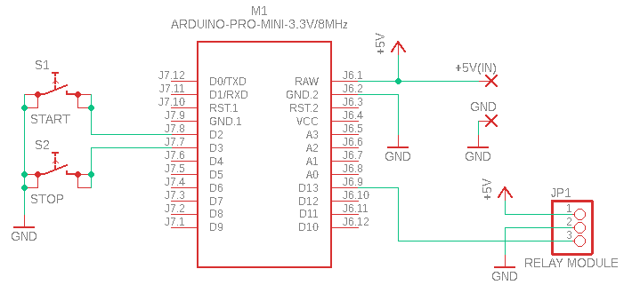
Below you can see the Pro Mini Start/Stop Switch schematic. The HLK-5M05 SMPS module is omitted on purpose to simplify this drawing!
Pro Mini programming still seems like a daunting task for many newbies. Here’s a simple guide for them https://wolles-elektronikkiste.de/en/programming-the-arduino-pro-mini
Relay & R-C Snubber: Note that high energy noise spikes are generated whenever current is interrupted through an inductive load connected through the relay contact. These electromagnetic noise spikes (EMI) may interfere with the sensitive electronic circuitry causing erratic operation and may also accelerate microcontroller failure.
An R-C Snubber is therefore recommended to suppress the “inductive kick back” from inductive loads that create an electro-magnetic collapsing field.
Applied across an inductive load, the R-C snubber (a series connected capacitor and resistor network) suppresses the electrical noise spikes to electronic circuitry and extends contact life on mechanical relays (by limiting the contact voltage at the time of contact opening when the contact gap is small).
This is a sample AC230V R-C Snubber circuit
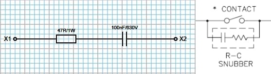
In practice, placing the R-C Snubber across the relay contact in many cases can work as well, but according to experts, it should be wired directly across the load for maximum effect.
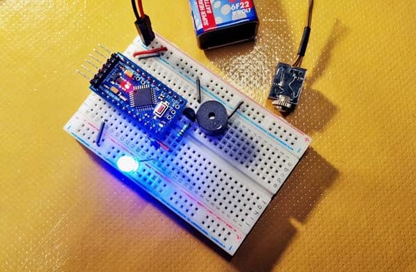
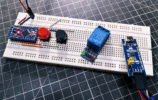
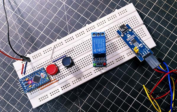
To be honest, I made this project a few weeks ago and installed the final prototype in a small pump house. So, I do not have any photos of it to share right now. Anyway, below you can see the snapshots of my half-baked breadboard setup (taken on my smartphone) that Google Photos (https://www.google.com/photos/about/) fortunately backed up at the time!
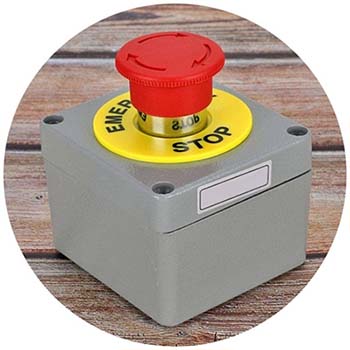
That’s all for now. The next in this series is the story of my quick experiments with an emergency stop switch. Goodbye until next time!