Described here is the do-it-yourself project of a simple self-dimming lamp. The self-dimming lamp is powered by a rechargeable 9V battery and features a push-button switch that triggers one bright LED as the emitter and a tiny microcontroller as the master brain. With an auto-dimming variable level light output, this portable LED lamp is well-suited for bedrooms, kitchens, corridors, staircases, and around the home.
Let’s begin by studying the schematic!
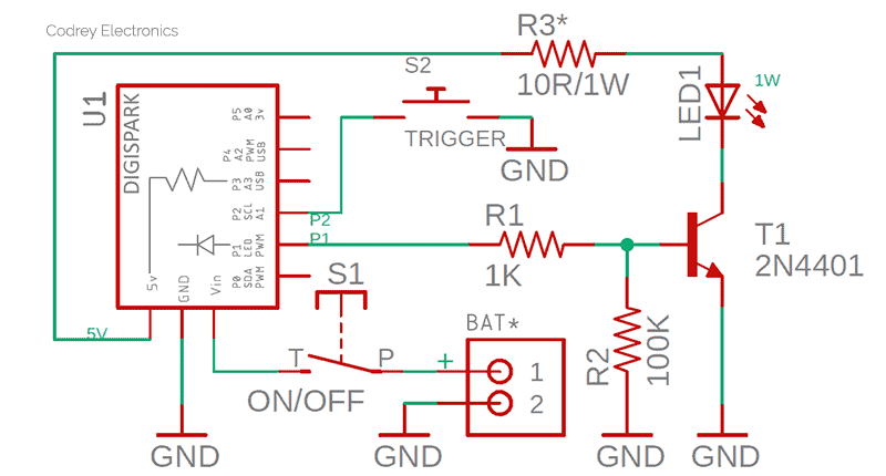
As can seen in the above schematic, this adaptable design is centered around the quite popular and ridiculously cheap Digispark Attiny85 Development board (U1), which is powered by a 9V lithium-ion battery through a 2-pin JST connector (BAT). The main power on/off switch (S1) is wired between the + pin of the JST connector and Vin pin of the Digispark board. One of the PWM output pin (P1) of the Digispark is routed to the LED driver transistor 2N4401 (T1), while its next I/O (P2) is wired to the trigger switch (S2) which is nothing but a normally-open momentary push button switch. The regulated 5V DC catered by the onboard 78M05 linear voltage regulator of Digispark is used to energize one 1W white LED (LED1) through a 10Ω/1W current-limiting resistor (R3).
It’s time to check the parts list!
- U1: Digispark Attiny85 Development Board
- T1: 2N4401 NPN BJT
- LED1: 1W Warm White LED
- R1: 1K ¼ w Resistor
- R2: 100K ¼ w Resistor
- R3: 10Ω/ ½ w or 1 w Resistor
- S1: SPST Slide Switch
- S2: Momentary Push Switch (normally-open)
- BAT: 2-pin JST connector
- Battery: 9V/500mAh Rechargeable Li-ion Battery
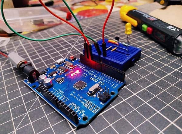
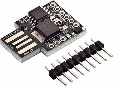
Below is a closeup of the Digispark Attiny85 Development Board used in this project. Note that the Digispark board has two onboard LEDs – the first one is a simple 5V power supply indicator LED and the second is a ‘user’ LED connected to its P1 port (PB1 of the Attiny85 microcontroller).
Working of this circuit is very simple because of the clever code running in the background. The white LED in the powered circuit will lit up always but only with a very dim light. However, the LED brightness increases gradually up to a certain level when the trigger switch is closed, and if the trigger switch is opened it comes back to the default light level. Interesting, yeh?
This is the Arduino-style Digispark code for this project:
/*
 * Self-Dimming LED Lamp v1
 * DIY Hobby Electronics Project (uC-Based)
 * Key Hardware: Digispark Attiny85 Dev. Board
 * Read the article for more information!
 * Author: T.K.Hareendran/03-2021
*/

#define LAMP_PIN 1 // P1
#define SWITCH_LAMP_PIN 2 // P2
#define MAX_LIGHT 250 // Maximum Light
#define MIN_LIGHT 25 // Minimum Light
#define REG_STEP 10

byte setpoint;
byte value;
unsigned long timeforlightstep;

void setup() {
  pinMode(SWITCH_LAMP_PIN, INPUT_PULLUP);
}

void loop() {
  if (!digitalRead(SWITCH_LAMP_PIN)) setpoint = MAX_LIGHT;
  else setpoint = MIN_LIGHT;

  if (millis() > timeforlightstep) {
    timeforlightstep = millis() + (unsigned long)REG_STEP;
    if (value < setpoint) value++;
    if (value > setpoint) value--;
    analogWrite(LAMP_PIN, value);
  }
}
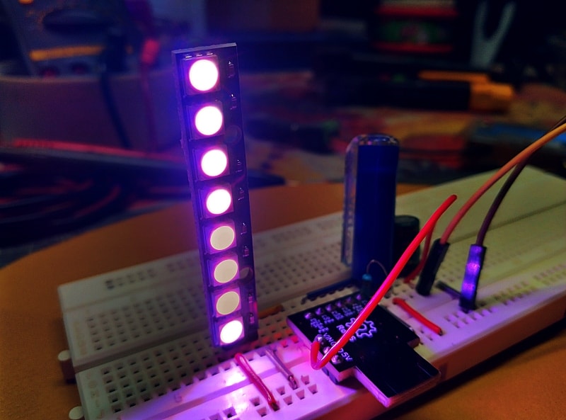
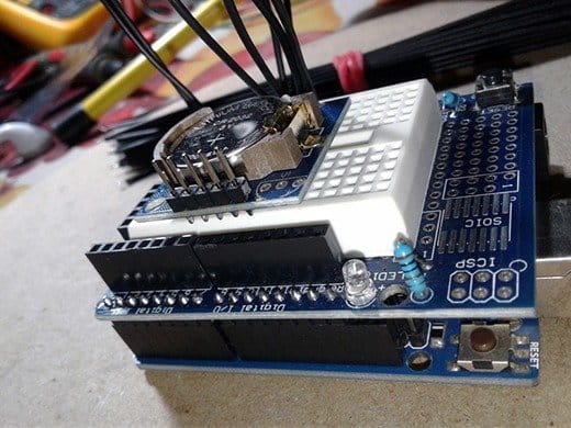
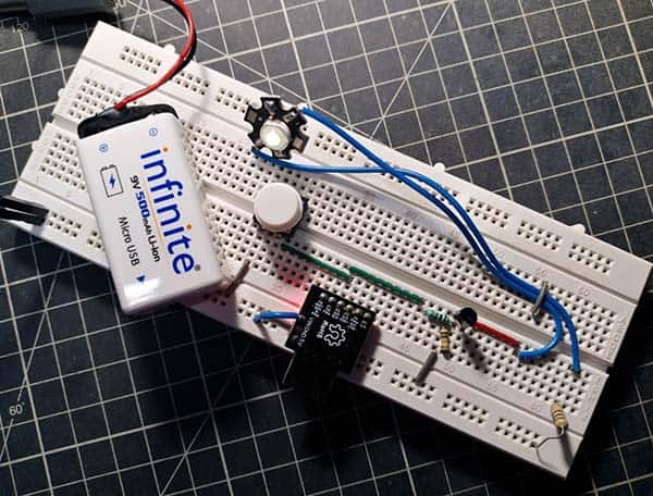
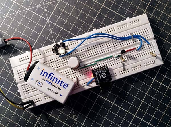
The quick test was done by assembling the circuit on a standard breadboard. Below shows my breadboard setup.
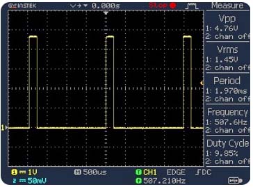
While testing my prototype, it worked aright as anticipated. The pulse width modulation (PWM) frequency, when probed at P1, is around 507Hz, and the duty cycle changes from around 9.8% to 98% (default dim to maximum bright) upon the trigger button action. Below is a casual oscillogram captured at that time.
Author’s Note
Now note that even though the white LED comes mounted on to special metal-core (MC) star PCB that draws some heat away from the LED, it’s slightly underdriven by the 10Ω series resistor. It’s intentional because during testing I don’t have a proper LED heatsink assembly handy. This will work for normal situations but for operating the LED with maximum efficiency and maximum potential, there’s a need to employ a constant current source LED driver rather than using a bulky series resistor. Further, it’d be better to replace the BJT with a logic-level MOSFET but after doing a little design alteration. And indeed, there’re such things out there – even I’ve a few IRLZ44 and IRL540 MOSFETs in my drawer.
Finally, the main reason why I designed this self-dimming lamp is due to its low cost, extreme compactness, and the fact that it can work as a cute night lamp for my bedroom by rendering a feeble brownish-yellow glow. Nevertheless, it’s always ready to go strong when absolutely essential!
Useful Links
- 2N4401 Datasheet http://www.farnell.com/datasheets/661741.pdf
- 1W White LED Generic Datasheet http://www.farnell.com/datasheets/1636581.pdf
- 9V Rechargeable Battery Guide https://www.codrey.com/electronics/9v-rechargeable-battery-right-wrong/
- Digispark Guide https://digistump.com/wiki/digispark
- Attiny85 PWM Primer https://www.electroschematics.com/attiny85-pwm-primer-tutorial-using-arduino/
- IRLZ44 Datasheet https://www.vishay.com/docs/91328/sihlz44.pdf
- IRL540 Datasheet https://www.vishay.com/docs/91300/sihl540.pdf