You cannot prevent the power grid from going down and up, but you can take steps to ensure that an electrical disturbance does not take your sensitive electronics devices down with it.

When power is being restored after an outage a lot of switching may have to take place, and each switching operation induces a potential spike, dip, or surge. Spikes are short-duration rapid positive or negative voltage transitions superimposed on the mains waveform.
Power spikes (and surges) can degrade, damage, or destroy electronic instruments. The best way to avoid damage from the spike/surge is to unplug devices that are very sensitive to voltage fluctuations, but that’s practically out of the question (https://www.electroschematics.com/power-back-surge-protection-circuit/).
The start & restart timer switch presented here is in fact a power-on delay timer that can be used to introduce a little delay before switch on the main input supply to any equipment. This obviously protects any electrical or electronic equipment and appliance from the aforesaid electrical nuisances to a great extent!
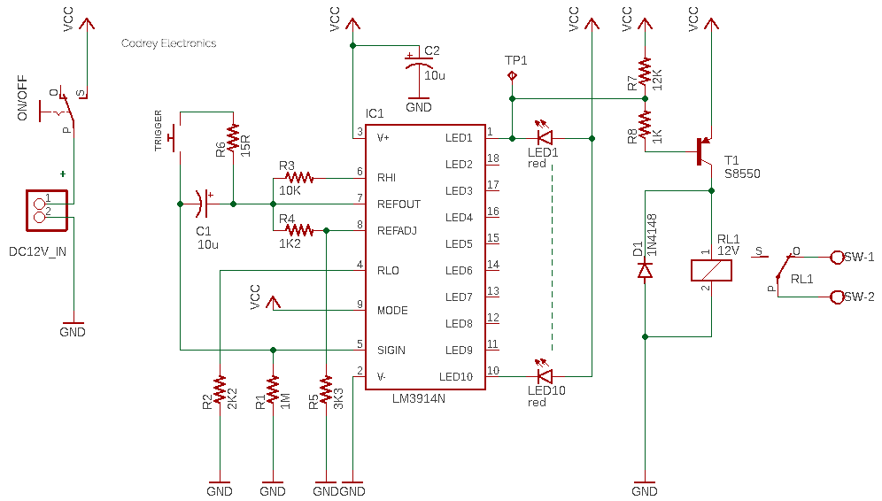
As you can see in the schematic above, the start & restart timer design is merely based on the ubiquitous dot/bar display driver LM3914 (IC1). The LM3914 is a monolithic integrated circuit that senses analog voltage levels and drives 10 LEDs, providing a linear analog display. A single pin changes the display from a moving dot to a bar graph. The current drive to the LEDs is regulated and programmable, eliminating the need for resistors (https://www.ti.com/lit/ds/symlink/lm3914.pdf).
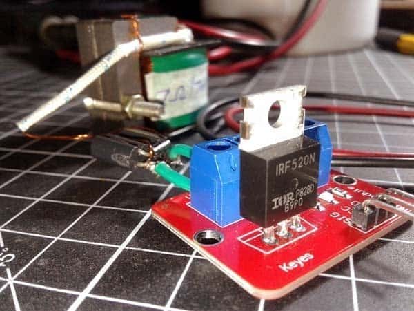
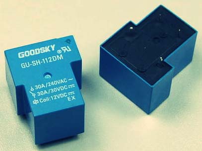
I tested my design on the breadboard using a HF115F (12VDC) sub miniature intermediate power relay (https://www.alliedelec.com/m/d/ee6a7104e2dceec38a8bad4d6e30e513.pdf). However, it is recommended to use T9o series power PCB relay (https://media.digikey.com/pdf/Data%20Sheets/Tyco%20Electronics%20P%20B%20PDFs/T90_Rev0214.pdf) for high capacity AC loads.
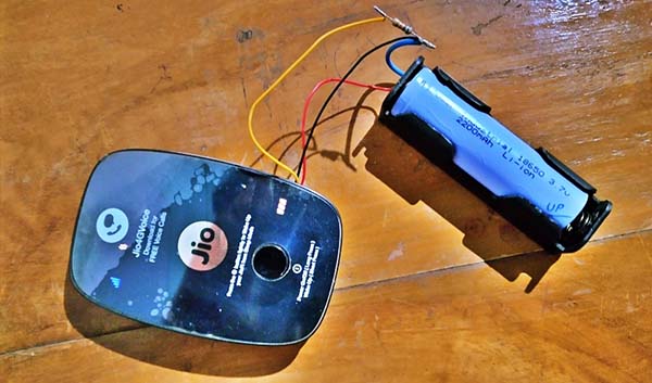
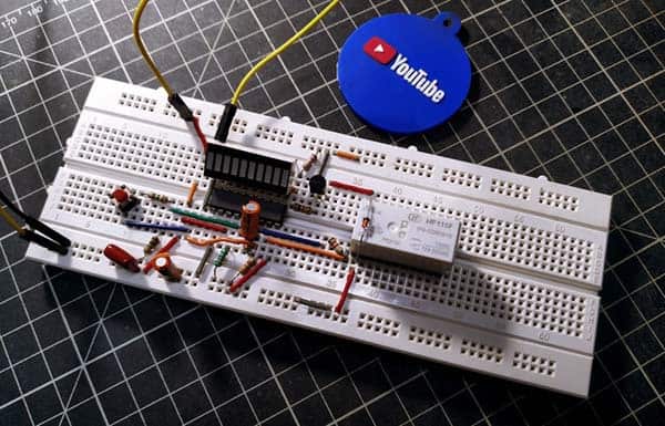
This is my breadboard setup. You can follow this link to watch a quick test video https://www.youtube.com/watch?v=M8kMya67-80
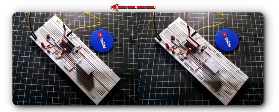
More quick test snaps:
Some time ago, while doing a random Google search for new ideas, I came up with an amazing idea to use LM3914 IC as a countdown timer rather than just a voltmeter display (thanks to that anonymous circuit designer). After that, I changed the original idea slightly, in my own way!
The LM3914 IC is a linearly-scaled unit specifically tailored for use in LED voltmeter applications in which the number of illuminated LEDs gives a direct indication of the value of an input voltage. This moderately complex IC has ten voltage comparators, each with its non-inverting terminal taken to a specific tap on a floating precision multi-stage potential divider and with all inverting terminals wired in parallel and accessible via input pin 5 and a built-in unity gain buffer amplifier. The output of each comparator is externally available and can sink currents up to 30mA (sink currents are internally limited but can be set via a single external resistor).
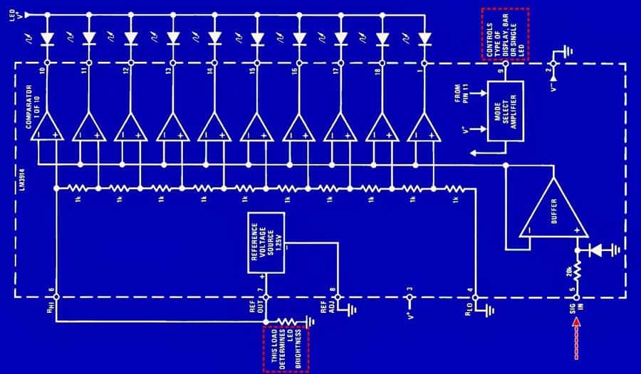
Since LM3914 senses an analog input voltage and drives the LEDs depending on the level of the input voltage, we can provide the input voltage from a discharging capacitor. And the time required to turn off all LEDs can be set to specific intervals, depending on the resistive load which discharges the capacitor. This is how the countdown timer is made here. The LED display is a cheap 10 LED (red) Bar graph.
This circuit uses the internal current source of LM3914 to charge the 1ouF capacitor (C1), and a 1M resistor (R1) is used to discharge the capacitor. When the last LED (LED1) is off, the S8550 transistor (T1) drives the 12V relay (RL1). Note that the relay’s common (C) and normally-closed (NC) contacts are used to switch the connected load. By altering C1-R1 values, you can increase or decrease the countdown period at ease (10 seconds default).
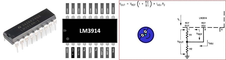
On a side note, the reference is designed to be adjustable and develops a nominal 1.25V between the REF OUT (pin 7) and REF ADJ (pin 8) terminals. The reference voltage is impressed across program resistor R1 and, since the voltage is constant, a constant current I1 then flows through the output set resistor R2 giving an output voltage of VOUT = VREF (1+ R2/R1) + IADJ R2.
The current drawn out of the reference voltage pin (pin 7) determines the LED current. Approximately 10 times this current will be drawn through each lighted LED, and this current will be relatively constant despite supply voltage and temperature changes. Current drawn by the internal 10-resistor divider, as well as by the external current and voltage-setting divider should be included in calculating LED drive current.
My circuit is powered from 12V DC and the breadboard prototype takes a total current of less than 100mA. The countdown process is started when power is applied/re-applied to the circuit. All LEDs will be on and after a few moments will begin to turn off starting from LED10. The relay is on initially (load disconnected) and remains in that state until the countdown timer stops (load connected). The momentary push-on switch (TRIGGER) can be used to manually initiate the countdown process at any time if necessitated.
In this post, you will see how to build a countdown timer using the LM3914 dot/bar graph display IC. I’m glad the weird idea turned into a real-world device. I hope this post will be helpful for those interested in LM3914. Creating this project was definitely fun and excellent learning practice. That experience helped me a lot to create this write-up that describes a fascinating analog project built using only a handful of components.
As Mary Kay Ash said, a mediocre idea that generates enthusiasm will go further than a great idea that inspires no one!