Nowadays you can see many dc power supply modules equipped with an additional remote-controlled shutdown (or on/off) feature. It allows you to control the power supply output with a signal switch or transistor.
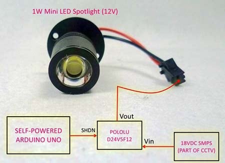
Some time ago I needed to make a belittled corridor night light with cyclic on/off features using the D24V5F12 module from Pololu. The hobby project needs a few sweetenings so I will only publish it here after a few weeks. As you can see, that module has a shutdown input that can be controlled from external electronic circuitry.
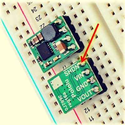
According to Pololu, the extremely compact D24V5F12 synchronous buck voltage regulator module takes an input voltage of up to 36V and efficiently reduces it to 12V while allowing for a maximum output current of 500mA. The module also has a power-save mode that activates at light loads and a low quiescent (no load) current draw, which make it well suited for low-power applications that are run from a battery. The shutdown (SHDN) pin of the module can be driven low (under 400mV) to turn off the output and put the module into a low-power state. Since there is an onboard 100KΩ pull-up resistor, you can left the shutdown pin unconnected to run the module permanently.
In order to wake and halt the voltage regulator module in the cycle, I quickly chose an Arduino microcontroller board. This was intentional because I was sure that by updating the code, I would be able to easily integrate more functions into the existing design later. This is the blueprint of that little project.
In order to wake up and halt the Pololu D24V5F12 module, and thus the LED spotlight wired across its output, every forty-five seconds, I had to add a timer to the code. I imported the “Timer” library and uploaded the following code to my Arduino Uno (I set the interval to fifteen seconds in the quick test, just to make sure it works).
#include "Timer.h" // Timer Library

const int HB = 13; // Heartbeat LED (onboard)
const int SW = 12; // Wake/Halt Signal D12

const unsigned long PERIOD_SW = 45000; // 45sec

Timer tk;

void setup(void)
{

  pinMode(HB, OUTPUT);

  pinMode(SW, OUTPUT);

  tk.oscillate(HB, 100, LOW);
  tk.oscillate(SW, PERIOD_SW, HIGH);
}

void loop(void)
{
  tk.update();
}
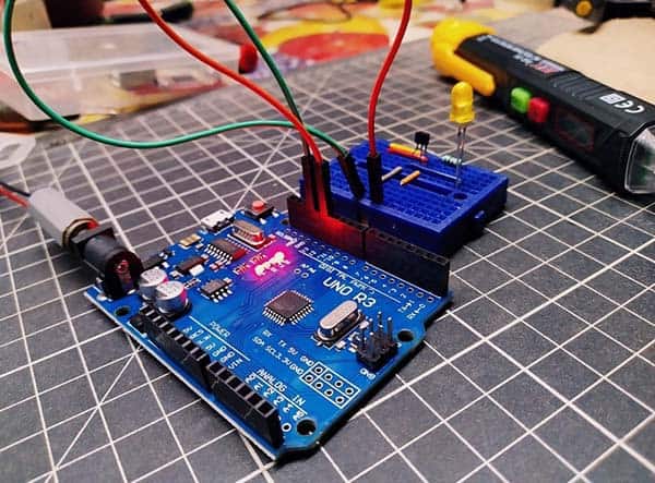
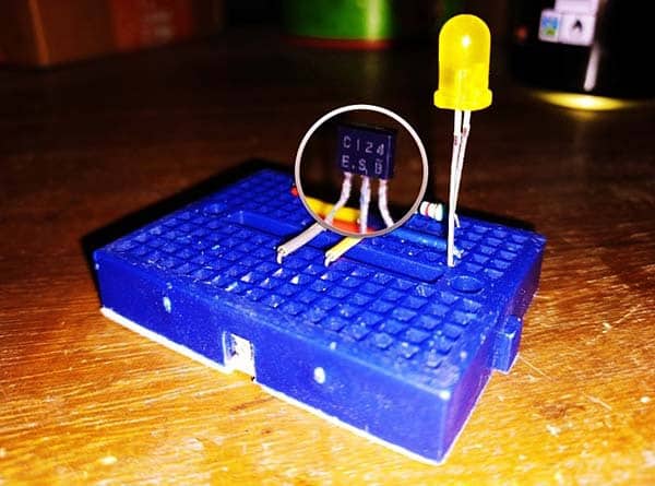
Once I had finalized my idea, I tested the Arduino hardware off my mini breadboard just to make sure that what I was doing was working. It works!
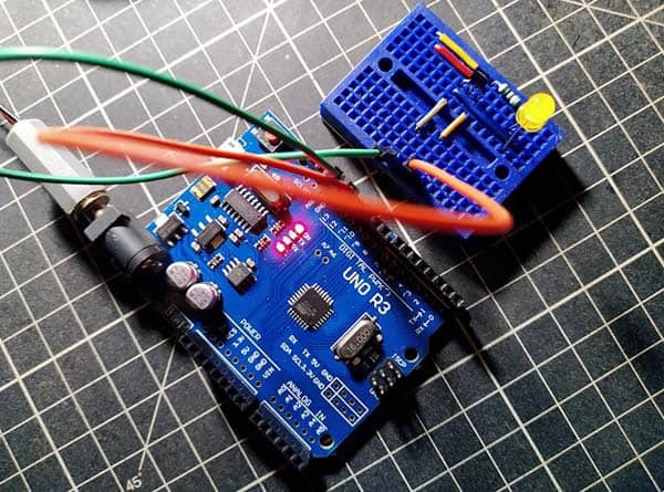
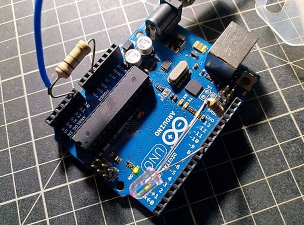
I then went ahead, tweaked the code, and linked the rest ( Pololu module & LED Lamp) onto the core electronics. Hope to have it in the corridor for a while!
Below you can find the schematic of the Arduino Uno hardware setup. Needless to say, the 2-pin connector (SHDN) should go to the Pololu D24V5F12 module’s shutdown interface (SHDN and GND).
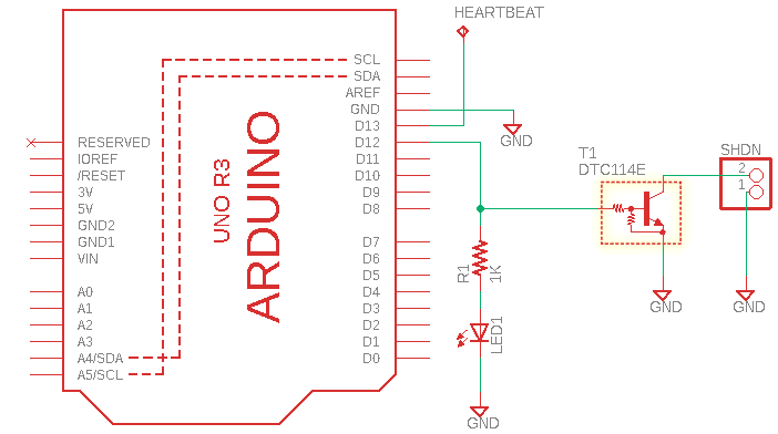
As you might have observed, there’s a strange transistor DTC114E (T1) between D12 output of Arduino Uno and Pin 2 of the CN1 connector. The DTC114E is nothing but a small-signal “digital” NPN transistor that has an integrated base bias resistor network (10KΩx2). This series of transistors is designed to replace a single device and its external resistor bias network. The Bias Resistor Transistor (BRT) contains a single transistor with a monolithic bias network consisting of two resistors (a series base resistor and a base-emitter resistor).
This is the pin assignment of a TO-92 package DTC114E Transistor:
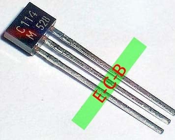
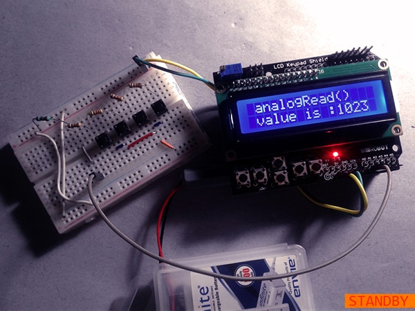
I have a good stock of these DTC-series BRTs. So, I tried my breadboard version also with a DTC124E (just a sanity test). Note that the DTC124E comes with 22KΩx2 base bias resistors.
- DTC114 Datasheet https://www.onsemi.com/pdf/datasheet/dtc114e-d.pdf
- DTC124 Datasheet https://www.onsemi.com/pdf/datasheet/dtc124e-d.pdf
- Pololu D24V5F12 Module https://www.rhydolabz.com/interfacing-modules-c-80/pololu-12v-500ma-stepdown-voltage-regulator-d24v5f12-p-1579.html
Since I need to avoid the effect of delays (I’ve a reason to do so – will explain in the sequel of this post), I’ve used a bit old Timer Library. Using timers instead of delays can improve the functionality of many Arduino projects. As with everything, however, it’s not okay for every occasion (it might make your final code more complicated), so see if this would work for you before having a go with various Timer Libraries (http://www.doctormonk.com/2012/01/arduino-timer-library.html).
Don’t forget to check out this GitHub link https://github.com/brunocalou/Timer
Also, in the Arduino Sketch shared here, the onboard LED (D13 LED) is configured as a heartbeat indicator but that’s just a “luxurious” (or useless) addition, doing nothing for the real intent of the project. Therefore, you can simply omit it by modifying the code – give retouches if necessary.
Below is a bit different experimental code for the same hardware setup – this time without using any Arduino Timer Libraries. In the code, you can easily change the wake and halt duration to adjust the cycle times (values in milliseconds). Note at this time too that, as D12 goes HIGH, the polo module turns off, and vice versa because T1 reverses the control signal.
const int shdnPin =  12; //D12
unsigned int switchState = HIGH;
long time1 = 5000;//Milliseconds
long time2 = 10000; //Milliseconds
unsigned long previousMillis = 0;
void setup() {

  pinMode(shdnPin, OUTPUT);
  switchState = HIGH;
  digitalWrite(shdnPin, HIGH);
}
void loop() {

  long currentMillis = millis();
  if ((switchState == LOW) && (currentMillis - previousMillis >= time1))
  {
    switchState = HIGH;
    previousMillis = currentMillis;
    digitalWrite(shdnPin, HIGH);
  }
  else if ((switchState == HIGH) && (currentMillis - previousMillis >= time2))
  {

    switchState = LOW;
    previousMillis = currentMillis;
    digitalWrite(shdnPin, LOW);
  }
}
Now to the concluding remark! Yes, I know this is a weird project idea, but let it be so. As mentioned earlier, I will be presenting an upgraded do-it-yourself project soon. So, stay tuned!