What is sound energy and how does it interact with a non-Newtonian fluid (https://en.wikipedia.org/wiki/Non-Newtonian_fluid)?
This is just an attempt to get a variety of non-Newtonian materials “dancing” on a subwoofer using sound waves. Inspiration – A YouTube video https://www.youtube.com/watch?v=QROAuD-XssE
Of course, this is a simple do-it-yourself electronics project, however, it would be better to call it a funny science (physics) experiment for the curious kids.
What You’ll Need (& Build)
For this project, you need to prepare a simple experiment setup from a set of ready-made things. The key things are:
- Subwoofer
- Subwoofer Amplifier
- Plastic Wrap
- 40/50Hz Test tone
- Corn-starch, Water, and Food Colour
How to Start (& Run)
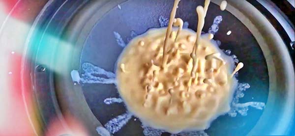
First of all, make slime out of cornstarch and water. For this, simply mix 4 ounces of corn starch and ½ cup of water until you get a soft and sticky substance. Great, now you have made a non-Newtonian fluid whose viscosity changes on the applied force!
Now take your subwoofer and put plastic wrap over it to protect it from the corn-starch slime. Next, pour the corn-starch slime on the plastic wrap on the subwoofer and add some food color. Finally, connect your subwoofer to the subwoofer amplifier, play the test tone from your smartphone (or computer) through the subwoofer, and watch what happens!
This is the link to download a sample test tone (14MB) from the author’s Google Drive https://drive.google.com/file/d/1bG9etays5Iow6vze46CBfvw_tsPSjac1/view?usp=sharing

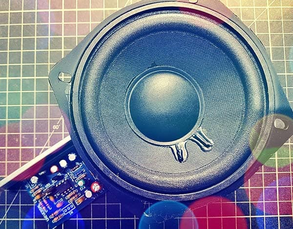
You don’t have to buy expensive electronics devices for this project. Almost all subwoofer and subwoofer amplifier can be used here. For example, my experimental setup consists of a 4-inch 40W subwoofer and a readymade minuscule 19W subwoofer amplifier module.
The subwoofer amplifier module designed to be operated from 12VDC power supply is actually a combination of a monophonic audio power amplifier and an active subwoofer low pass filter circuit. I bought them from Flipkart and successfully used for this project. That’s all!
Active electronics people do not find my lazy approach interesting because they always want to build something new themselves. I know, so I’m now giving some practical tips for those who want to use homemade circuits.
Subwoofers & Subwoofer Low Pass Filters
Stereo speakers are designed to optimally play at specific frequencies, and a subwoofer is all about that bass. It’s the speaker that delivers the lower frequencies – specifically 20-200 Hz – that a traditional two-channel or surround sound setup can’t reproduce on its own. These low frequencies come from instruments such as the kick drum, bass guitar, and pipe organ, as well as movie sound effects like explosions (https://en.wikipedia.org/wiki/Subwoofer).
Since a subwoofer plays extremely low frequencies, the subwoofer amplifier is basically configured to handle those audio signals of low frequencies (20Hz and 200Hz). Note that subwoofers will become distorted and torn if high-frequency music is played through them.
So, this calls for a special low pass filter (LPF) circuit usually known as a subwoofer filter. There’re both passive and active subwoofer filter circuits carefully designed to pass only low-frequency bass signals. In other words, a subwoofer filter is an electronic device that removes high frequencies from audio signals that are sent to subwoofer speakers. In practice, the audio signals are filtered at first by the subwoofer filter to remove the high-frequency signals. And then, selected low-frequency signals are amplified with the help of the subwoofer amplifier. That’s it.
DIY Passive Subwoofer Filter
This session deals with the circuit of a simple first-order passive low pass filter which is designed to be wired before the audio power amplifier used to drive a subwoofer. This little circuit has an adjustable cut-off frequency between 20Hz and 200Hz, and it works well with line-level signals. Line level is the specified strength of an audio signal used to transmit analog sound between audio components (https://en.wikipedia.org/wiki/Line_level).
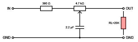
As you can see here, a simple first-order RC passive low pass filter can be easily built by connecting together in series a single resistor with a single capacitor. This type of filter is also known as a “one-pole filter” because it has only one reactive component in the circuit – the capacitor!
This circuit is cheap and easy to build, but remember, its cut-off frequency actually depends on the output impedance of the audio input source (your smartphone/computer) and on the input impedance of the audio power amplifier (your subwoofer power amplifier).
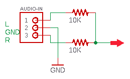
Since the bass information is present in both Left & Right (stereo) channels of the audio input source, the signal for the subwoofer filter can simply be tapped from one of them, or combine them using just two resistors as shown below (for reference only).
Side Note: Generally, the input impedance to an audio amplifier is comparatively high, 10K to 100K is the usual sort of range I find, though some can be as low as 1K. Luckily, even something as low as 1K will be driven easily by most audio circuits whether they’re designed to drive headphones or not.
DIY Active Subwoofer Filter
Countless circuits for active subwoofer filters are available on the web. They are usually based on op-amps such as NE5532, LM4558, and TL072 (look below). So, I don’t want to reinvent the wheel. Anyway, let me mention a few important things.
- NE5532 Datasheet https://www.onsemi.com/pdf/datasheet/ne5532-d.pdf
- TL072 Datasheet https://www.ti.com/lit/ds/symlink/tl074h.pdf
- LM4558 Datasheet http://www.htckorea.co.kr/Datasheet/Signal%20Conditioning/LM4558.pdf
As we can usually see, most of the active subwoofer filter circuits need a dual-power supply, which means, like +/- 12V. With a dual power supply, the V+ terminal of the op-amp receives a positive voltage, and the V- terminal connects to a negative voltage. Therefore, any input signal fed into the op-amp can swing from the positive voltage supply to the negative voltage supply, thus covering the full cycle of the audio signal. This a link for further reading http://www.learningaboutelectronics.com/Articles/Difference-between-a-single-and-dual-supply-op-amp.php
Well, here you can find a do it yourself active filter circuit for subwoofer with 4558D IC https://www.instructables.com/Low-Pass-Filter-for-Subwoofer-With-4558D-IC/
Side Note: A subsonic filter is a component on your audio system’s subwoofer that reduces the intensity of notes which come through at lower frequencies. It decreases the amplitude of those low notes that you feel more than you hear. To learn more about subsonic filters, check out this link https://decibelcar.com/subsonic-filter/
DIY Subwoofer Power Amplifier
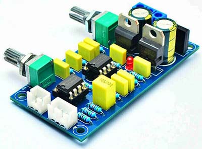
An audio power amplifier (https://en.wikipedia.org/wiki/Audio_power_amplifier) for the subwoofer can be easily assembled by a reasonably experienced hobbyist, it will take a somewhat longer time though. Buying a pre-wired subwoofer amplifier kit/board for the dancing slime project is also easy now. As can be seen, this is a cheap board version based on the venerable TDA2030A IC (https://www.st.com/resource/en/datasheet/cd00000128.pdf).
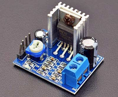
Read more about this board https://www.petervis.com/Electronics_Kits/tda2030a-mono-power-amp-module/tda2030a.html
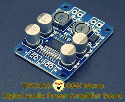
A number of Class D audio (https://www.analog.com/en/analog-dialogue/articles/class-d-audio-amplifiers.html) amplifier circuits and kits are also available for sale almost everywhere online, as well.
In Conclusion
You may be wondering why I don’t talk much about the dancing slime project. That’s is intentional because it’s an easily understood concept and therefore does not require further discussion. My purpose is to help you prepare the supporting electronics for your kid’s dancing slime experiments.
At this moment, let me make a confession, I’ve no test videos to show you. Trust me, when I finally drafted this post, it’s accidentally lost. My mistake. But one thing I noticed is that the vibration of the colored slime on the subwoofer seems to move very slowly when filmed on camera, but that’s not clearly caught by my naked eyes at that time. Weird!
Finally, whatever it might be, I’ll bring you a disco light project that gives some pleasing visual effects on the dancing slime soon. I have a couple of audio-controlled electronics projects on my list. We’ll see where it goes!