Thermo fans are an important part of thermal management for high-power electronics because when the temperature increases, performance can suffer, and beyond the point where performance degradation begins, excessive temperature causes catastrophic damage to delicate electronics parts.
Thermo fans (cabinet/enclosure/heatsink cooling fans) in electrical and electronic devices have been getting more and more efficient over the last years. However, in many systems, the thermo fans are always spinning at maximum speed – no matter if the ambient temperature is high or low. Some modern thermo fans feature inbuilt temperature controls, but they are usually a bit costly, thus not within the easy reach of an average electronics hobbyist.
So why not do something yourself?
Well, this article describes a simpler technique for automatically switching a thermo fan on/off based on the temperature level. The little trick presented here not only reduces the acoustic noise but also lengthens the fan’s lifetime significantly as the fan works only when the temperature level increases above a setpoint.
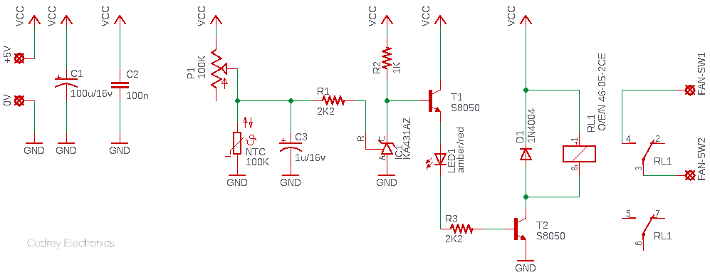
Circuit Diagram
Following is the circuit diagram of the automatic thermo fan switch.
Design Description
The circuit is designed for regulated 5V dc power supply operation. Since the overall current consumption is moderate, the entire circuit can be powered from the ‘logic’ power supply section of the device in which the thermo fan switch circuitry is proposed to be fitted for automatic cooling fan control. The first two capacitors (C1-C2) are simple power rail buffer/filter components.
A belittled type 100K negative temperature coefficient (NTC) thermistor is used as the temperature sensor here, and a 100K multiturn trimpot (P1) is added for adjusting the setpoint at ease. The specific NTC thermistor used in the prototype shows a zero-power resistance around 81KΩ at 29°C (room temperature), and it falls to around 41KΩ at 45°C.
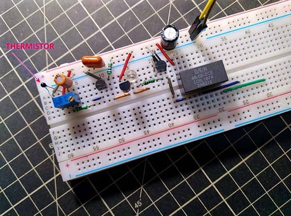
The KA431AZ (IC1), equal to TL431A, is a three−terminal precision adjustable shunt regulator diode. This monolithic IC voltage reference operates as a low-temperature coefficient zener which is programmable from Vref (2.495 typical) to 36 V with two external resistors. Here IC1 is configured in an unorthodox way to drive a 5V electromagnetic relay (RL1) via a pair of S8050 NPN transistors (T1-T2). LED1, which is a regular 5mm amber/red LED with a typical forward voltage (VF) of 1.6 to 1.8 V, functions as an over-temperature/fan-active indicator. Note that, around 4.3 V coming through the emitter lead of T1 (happens when the temperature rises above the setpoint) is routed to the base lead of T2 through LED1 and the associated 2.2KΩ resistor (R3).
The “2 Form C” 5V electromagnetic (or electromechanical) relay used in the breadboarded prototype is a type 46-05-2CE from O/E/N. Since it has a coil resistance close to 167Ω, the maximum operating current is well under 30mA. When taking this into account, the mighty S8050 transistor is certainly overkilled but it lets you use another relay, perhaps with a very low coil resistance, instead of the type proposed here.
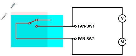
The common (3) and normally-open (4) contacts of RL1 can be used as an electric switch for the thermo fan as shown in the below wiring diagram. Further, RL1 provides perfect galvanic isolation, therefore you can safely run any thermo fan – be it 12 V dc or 24 V ac – through its switch contacts. As you can see, RL1 has a set of ‘free’ contacts as well, which might be helpful in certain applications.
Construction & Calibration
The entire electronics must be wired on a flake of zero PCB or customized PCB (never use a breadboard for the final build). While soldering the components, try to keep all components as close, and interconnections as short, as possible. This will (hopefully) provide robust protection from nasty oscillations. Since this section does not cover the smallest details of working with KA431 IC (everything is well-described in its datasheet), do take some time to walk slowly through the “stability boundary conditions charts” included in the application notes.
Initial calibration is in fact a tricky process to follow!
- Energize the circuit up with a regulated linear (or a switch mode) 5 V dc power supply (minimum 100mA output current).
- Connect a precise DVM or DMM across the capacitor C3.
- Slowly tune the multiturn trimpot P1 clockwise/counter-clockwise to get a readout of +2.499 V there (relay will be in off state). Caution: Never set the trimpot resistance value too low as it will kill the thermistor!
- Thereafter slowly heat the thermistor and observe the indicator LED1.
- LED1 will light up at a particular temperature (just over the setpoint temperature). The relay RL1 activates as well.
- Finally, connect a thermo fan to retest the functionality of the entire setup.
- Do over the calibration if necessary.
At this point, it is worthy to take note that a cooling fan is intended to keep equipment in an acceptable working environment, but that environment is not the same as the comfort space that we would like to experience. Rather, a higher working environment temperature is acceptable, and in most instances desired for electrical devices. As it seems, the acceptable working environment temperature for most electrical/electronic devices is circa 40°C (104°F).
Author’s Note
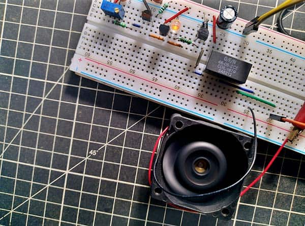
As usual, I built a quick prototype using a regular breadboard and tested it with a heavy-duty 12V brushless dc (BLDC) mini heatsink cooling fan I have in hand at that time.
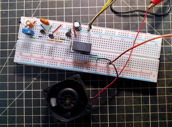
A little inelegant setup perhaps, but believe me, it worked! I’m happy to answer more questions about this simple experiment if you’d like.
Side Note: Thermistors (thermal resistors) are temperature-dependent variable resistors. As with a regular resistor, we can use a DMM to measure the thermistor resistance. The resistance value displayed then should correspond to the ambient temperature near the thermistor, and it will vary in response to temperature change.
On the application side, you can linearize thermistor response by placing a fixed resistor in series or in parallel with it – this improvement will come at the cost of some accuracy, though. It’s recommended on paper that the value of the additional resistor should be equal to the thermistor’s resistance at the midpoint of the temperature range of interest. Nevertheless, the series thermistor-resistor combination (P1+NTC), used in this design, provides a simple solution in the form of a crude voltage divider. In other words, the voltage divider converts thermistor resistance (and thus temperature) to voltage. You use this formula to calculate the voltage divider output voltage: Vo = 5V * (RNTC /(RP1 + RNTC )).
What is more, the B (or Beta) constant value indicated in the datasheet of a thermistor represents the relationship between the resistance and temperature over a specified temperature range. For example, “3950 25/50” indicates a beta value (K) of 3950 over a temperature range from 25°C to 50°C.
Closing Remark
Ultimately, this is not a well-designed thermo fan switch circuitry, but a crude experimental project for hobby and educational purposes. I’m assuming you know what you’re doing!
Datasheets
- KA431 Datasheet https://www.onsemi.com/pdf/datasheet/ka431-d.pdf
- S8050 Datasheet http://media.nkcelectronics.com/datasheet/s8050.pdf
- O/E/N 46 Series Relay Data https://pdf.directindustry.com/pdf/o-e-n-india-ltd/series-46/63536-147342.html