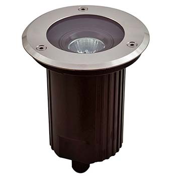
Why use an inground uplighter (buried uplight)?
The answer is simple – when lighting a static object with a buried uplight its visual impact can be stunning, whilst no one pays attention to that minuscule light module during the day!
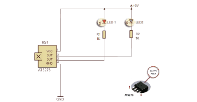
Interested? Well, in this post you can see the construction project of a simple yet fabulous inground uplighter. Okay, let us start with its circuit diagram…
The inground uplighter presented here is a bit unconventional because a flashing LED lamp is employed in this design. In many respects, it would be better than a continuous light because a flashing inground uplighter delights the senses more quickly.
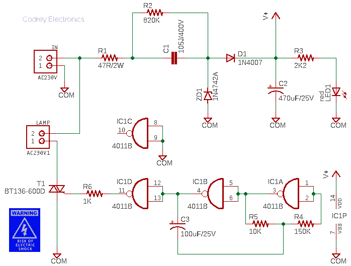
And for this reason, the design is centered around a quite popular and easily available CMOS chip – the CD4011B (IC1) – which is a Quad 2 input CMOS NAND Gate IC. The first two gates of IC1 are wired to make a low frequency oscillator (IC1A-IC1B), and the fourth gate is used as buffer (IC1D). The oscillator frequency is primarily determined by the R-C components R5 (10K) and C3 (100uF). Following the usual practice, input leads of the unused 3rd gate (IC1C) are tied to the common/ground rail (COM) of the circuit.
The output signal available through IC1D is then routed to a BT136-600D TRIAC (T1) via a 1K resistor (R6). The BT136-600D is in fact a 4A-rated planar passivated very sensitive gate four quadrant triac in a TO220 plastic package intended for use in general purpose bidirectional switching and phase control applications, where high sensitivity is required in all four quadrants. This device can be interfaced directly to microcontrollers, logic integrated circuits and other low power gate trigger circuits.
Note at this point, most electronics retailers sell triacs, however, it is common for most sellers to often supply a substitute component without even thinking. For this somewhat odd circuitry, it’s crucial that the triac must be a sensitive-gate type. Therefore, it’s important to be able to read a datasheet and find a right drop-in replacement part just in case your retailer does not sell the triac you’re looking for.
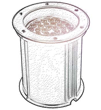
I decided the best way to get more compactness for my prototype was to use a small canister model enclosure (see my pencil sketch below). To do this I opted to use a true solid-state design, and that’s why a triac is used in the circuit rather than picking a comparatively beefy (and noisy) electromagnetic relay (there’re some other reasons too).
On the same grounds, a transformer-free power supply is deliberately incorporated in this design to power the entire electronics assembly.
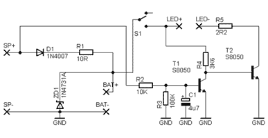
The key component in the capacitive power supply circuit is the high-voltage capacitor C1 (1uF/400V). Exploiting the reactance of a capacitor for supplying a small load from the AC power supply is not only elegant, but also simple and cost-effective, yeh?
Now about the function of the rest of the components seen there: During the positive half-wave, the zener diode ZD1 (12V/1W) operates as a voltage-limiting component. If the power supply switches on at the line voltage peak, an impermissibly high current would flow through ZD1, resulting in its destruction. So, resistor R1 (47Ω/2W) is connected on the line side to limit the current. However, it is better to use a 2W type 12V zener diode as ZD1. Likewise, there is no harm in using a 100Ω/2W resistor as R1. The diode D2 (1N4007) is a common silicon diode with the task of rectifying the ac voltage while the red LED (LED1) works as a power status indicator.
The electrolytic capacitor C2 (470uF/25V) is responsible for smoothing the output dc voltage. In a worst-case scenario it may happen that, when switching off without a load, C1 remains charged with the peak voltage of 325V. It is then the job of resistor R2 (820K/0.25W) to discharge C1 as fast as possible.

I opted use one AC230V DOB LED plate (9W) for the prototype as it fits nicely into the destined canister-style enclosure. I was pleasantly surprised at just how useable that nifty piece of electronics was (https://www.electroschematics.com/linear-led-driver/).
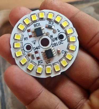
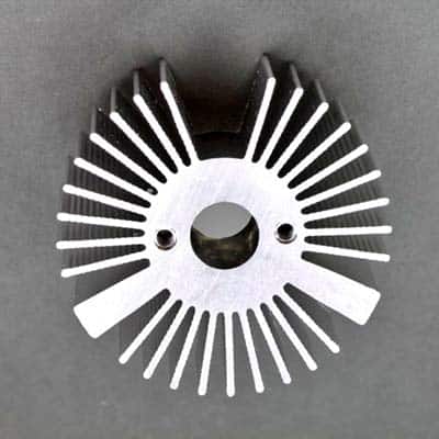
Be cautious, under no circumstances should the DOB LED plate be operated without a proper heatsink.
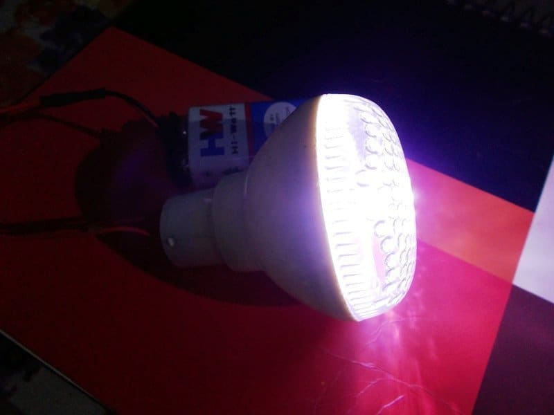
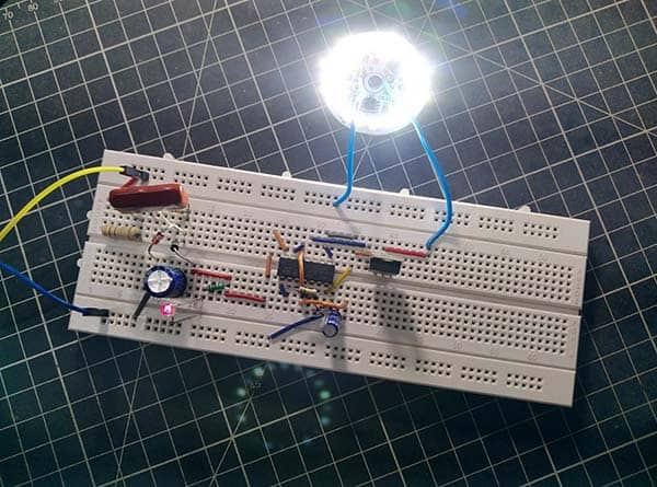
Before building a final model (for a lengthy field trial) with printed circuit board and handmade enclosure I decided to make a quick test setup on a breadboard (see below). You can choose to skip the breadboard build and to the final build but be sure to check all things thoroughly.
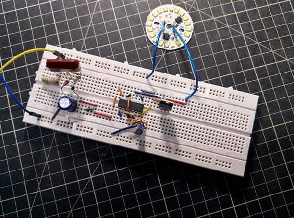
Needless to say, the setup worked aright as expected!
Electric Shock Warning!
This design has a ‘shocking’ drawback – it is devoid of any form of isolation from the fatal mains voltage. Therefore, make sure there are no exposed metal parts in your final build to avoid serious electric shock hazards!

Moreover, most inground uplighters inevitably will have some water ingress at some point, and this will not only cause the device to fail, but also the electric circuit to trip. The best practice is to use a high-quality waterproof enclosure for your build. Ideally, the electric supply to the inground uplighters should be an independent circuit with an independent safety/protection mechanism so that, if tripping issues do occur, they don’t affect the rest of the installation.
Symmetrical or Asymmetrical Light?
Now it is worthy to notice that for lighting designing, there are two options of light beams to consider when it comes to pick the right luminaire for a specific project – symmetrical beam or asymmetrical beam. A symmetrical beam distributes light evenly in all directions, so it is good for wide-area general lighting and for visual tasks. On the other hand, asymmetrical luminaires are recommended for concentrating the light beam in one direction. Usually, inground lights have more symmetrical than asymmetrical beams (see below).
Further reading https://www.fireflier.com/difference-asymmetrical-symmetrical-lighting/

Where to from here?
There is plenty of room to develop this project further. You could include a photoresistor to detect day and night automatically. Another idea would be to include a little wireless remote-control module so you could switch the inground uplighter through a handheld remote controller. Well, let something more powerful gets in its way!