An audio-light modulator is a funny device that controls the intensity of one or more electric lamps in response to the audio signal input. Such a device is ideal to give the rhythm to any party or disco, and is very safe to use as it usually provides perfect galvanic isolation between the audio signal and the mains voltage (otherwise any fault in the high voltage section of the device could completely destroy the low voltage section and give a fatal shock to anyone operating it).
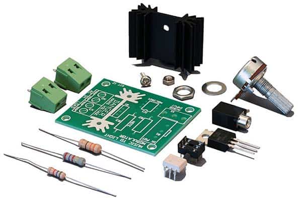
Nowadays, you can easily buy cheap and simple audio-light modulator kits (also known as music-to-light modulator kits) from many online electronics storefronts (see below). Almost all of them have a phototriac to drive a regular triac which further drives the high-voltage lamps wired through it.
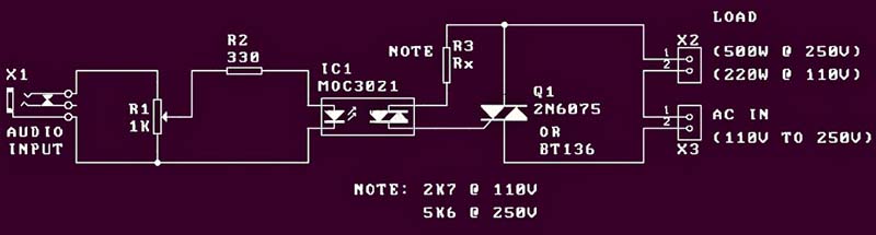
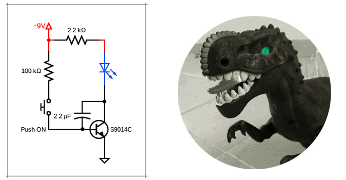
Following is the online schematic of a widely known and esteemed music-to-light modulator do-it-yourself kit. See it is utterly simple and self-explanatory!
Nevertheless, below you can see a bit different version of the audio-light modulator circuit developed recently by me. This oddball version obviously has a few more electronic components but that is with a purpose and intent – I will explain that in a new post.
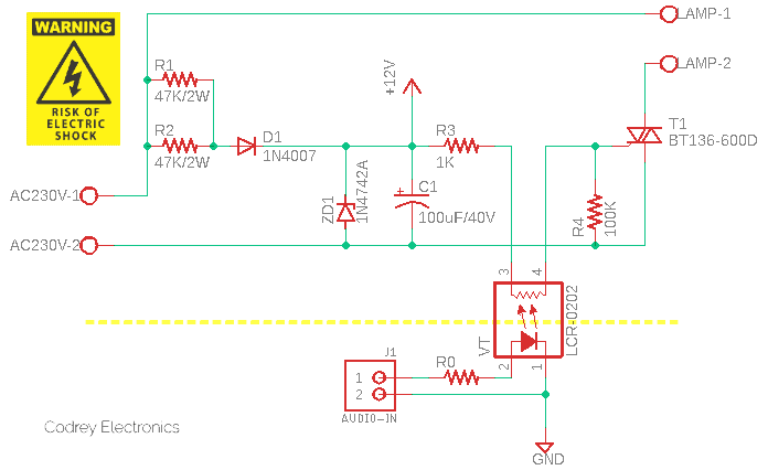
The first part of the circuit involves a low-current, low-voltage dc power supply comprising two resistors (R1-R2), one regular diode (D1), one zener diode (ZD1), and a buffer capacitor (C1). This part is directly connected to the AC230V input to derive a regulated 12VDC output.
The last part is a sensitive-gate power triac BT136-600D (T1) which is able to drive AC230V lamps rated up to 4A. For small lamps, it might be okay to operate the triac in free air, a suitable heatsink is recommended though.
Now to the middle part of the circuit i.e., to the core of this audio-light modulator design. Since I’ve plans to enhance this crude design later, an analog optocoupler is preferred here rather than following the traditional concept of using a phototriac. So, my quick pick is an available Vactrol (LCR-0202) which I already tried in a few little projects before. The point of the Vactrol is to receive audio signals from an external audio source as well as firing the triac through its photocoupler mechanism. Given that resistor R3 has a value of 1KΩ and the positive rail is 12V, VT can fire T1 aright. When the LED inside VT gets illuminated by an audio signal input, the 12V goes through R3 and the internal photoresistor of VT to fire T1. This makes a flash in the connected AC230V lamp(s). It must be noted that gate trigger is characterized in terms of gate trigger voltage (VGT) and gate trigger current (IGT). The gate trigger current varies with the gate pulse width, and it is evident that there is a minimum gate charge needed to trigger the triac (more on this later).
Going to resistor R0, it ensures that the Vactrol won’t be wrecked by an accidental overdrive. The recommended input current of the LCR-0202 Vactrol is 0-20mA (40mA max), and the recommended input voltage is 1.60-2.5V. You have to do your homework well to set the correct value of R0, naturally grounded on your specific application. Although some research or testing may be required, I think you should be able to do that.
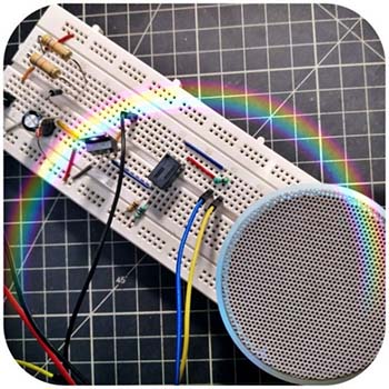
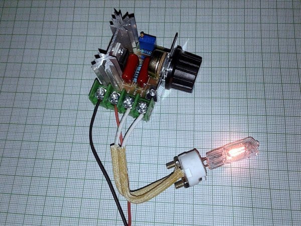
Even though it is a very bad practice, I rigged up my test circuit on a standard breadboard as shown below. More work will be done soon to refine this.
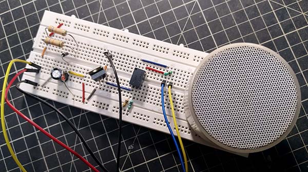
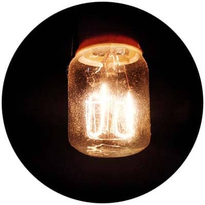
And then, simply tapped the “line-level” output (dc-coupled on purpose) from a cheap Bluetooth speaker to feed it (R0 = 680Ω). The electric lamp used is an AC230V refrigerator bulb I have in hand at that time. Believe me, the cute yellowish light reacts fabulously well to every music I feed (sorry for excluding the quick test movie)!
Side Note: An increasing number of audio interfaces now provide dc-coupled inputs and outputs to enable them to be used with dc signal control voltages. The dc-coupling is a circuit arrangement that allows both ac (e.g., audio) and dc (e.g., control voltages) to pass into (or out) of an amplifier or other circuitry.
Going Further…
Yeah, at this time first phase of this little project is complete! Oh, I hear that question – what is next? Perhaps, the next idea is to build a mighty multi-channel music visualizer. My analog idea so far is to separate the input audio signal into separate frequency bands and then light each lamp channel up correspondingly. The trickiest part is the design of suitable filters (for different frequency bands) to control the multi-channel lamp driver. There are many ways to do this, the easiest way is to employ op-amps together with some passive components. Looks interesting too?
Related Resources
- Bluetooth Speaker Hack https://www.electroschematics.com/bluetooth-speaker/
- Homemade Vactrol https://www.codrey.com/electronics/analog-optical-isolators/
- LCR-0202 Intro https://www.codrey.com/learn/analog-optocouplers-quick-starter/
- LCR-0202 Datasheet http://pliki.aksotronik.pl/lcr0202.pdf
- BT136-600D Datasheet https://www.mouser.in/datasheet/2/848/BT136-600D-1666873.pdf
- 1N4742A Datasheet https://www.mouser.in/datasheet/2/308/1N4736AT-D-1801584.pdf
Excellent and very informative article, thank you.
Regarding active filters: I made a 3.3kW, 3-channel sound to light system that used a low pass, band pass and high pass set of active filters, based on the old 741 op-amps, that worked from bass, middle and treble frequencies in the sound track. These filters fed a transistorised zero-voltage detector that produced a pulse at the zero voltage crossing point of the ac mains cycle, thus minimising interference and increasing bulb life. These pulses fed a bank of ITT pulse transformers, tested to 5kV by them (no opto-isolators then !) the secondaries of which linked directly to the new, (at the time) innovation from Texas Instruments – the triac. These effects started the Disco Revolution back in the day.
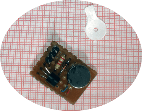
I found another use for the active filter: Back in the ’70’s in my days as a club DJ big strobes were practically unobtainable, and ones that were triggered by the bass beat in a song did not exist at all, outside of Hawkwind’s collection of mighty 4 channel Rainbow Strobes.
I found a bog standard battery driven little ‘photoflash’ circuit, and beefed it up to work direct-on-line (no isolation Tx – would have made it too heavy) from the 240V mains – the upgraded PSU developed well over 300V peak to a set of 3 massive, 5 Joules each, Xenon strobe tubes soldered into an Octal valve plug with their trigger poles commoned. A small value WW resistor was added to prevent self conduction of the tubes. The power to drive the tubes was stored in a bank of salvaged 32uF 600V power factor capacitors, with the safety resistors taken out (Health and Safety? – Oh right – it’s the 1970’s). The trigger cct. was built using a 741 op-amp in an active low-pass filter that took a signal from the speaker cabinet and the o/p sent via an isolating pulse Tx to a UJT feeding the trigger Tx that made the 4kV pulse to ionise the tubes into conduction.
The reflector was made from an old silvered glass footlight reflector salvaged from an Edwardian theatre demolition – it was just over a foot across. The effect was absolutely awesome. Dancers appeared to be in ‘stop motion’ as the beat from the disco track matched their rhythm.
I got paid serious money building and hiring these effects out to other club DJ’s, also. Great times !
kev: Thank you for the inspirational feedback and for taking time to share your thoughts that will be useful to other readers too!
If my memory serves me right, in the 80’s I published a couple of sound-activated incandescent lamp projects with 3-channel active filters (LM324-based) in Electronics For You magazine. But it’s wired around regular stepdown transformers as input signal isolators (your ITT pulse transformer concept is very elegant and nostalgic).
It’s also very interesting to note about your photo flashgun hack attempts. I only have a very limited experience with Xenon tubes, maybe I can find a few in my junk box, though. But in some audio level display projects I used standard neon-glow lamps. Audio-gated HV oscillators were used to drive the glow lamps (analog is always fun).
Even after 36+ years of designing and posting electronics circuits, your note has filled in some gaps in my knowledge. Wish you good luck with all your projects 👍