I’ve been asked if I could post a little primer on key components widely used in guitar electronics and special-effect units. While there’re no solid plans to do so yet, I was thinking about what to cover in such a simple write-up. It would be cool to have something ‘historic’, and even better if it’s still useful. While I was thinking more along the way, I was again asked whether a note on analog optical isolators would be possible. Naturally, I awoke with a jump!
Preparing such a little primer, I know, isn’t that easy, there’re countless great write-ups floating around the web, most of them are focused on expensive or obsolete electronics, certainly not much useful for novices, though. Finally, I stumbled on the idea of a do-it-yourself project primer centered on an analog optical isolator, perhaps serves as an ideal igniter for a novitiate to rig up something that’s simple and funny enough to do in a lazy evening and yet yields some good results. Well, now is the showtime!
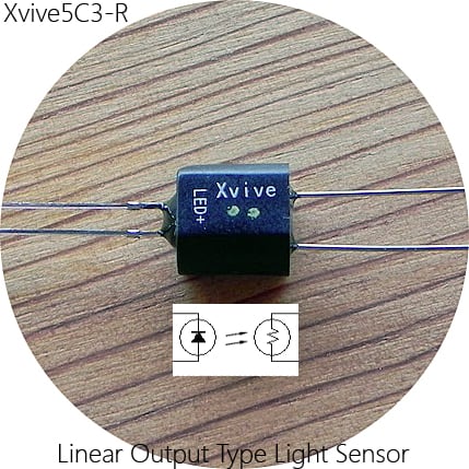
Nevertheless, there’re umpteen types of everyday optical isolators, but the most common is the LED/phototransistor type. An analog optical isolator (AOI) also uses an optical link between input and output, however, the input element is usually a light-emitting diode and the output element is always a photocell. Together, the optically-coupled pair in the analog optical isolator act as an electrically variable resistor.
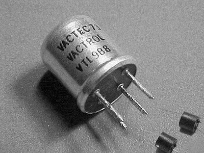
Vactrol® – Analog Optical Isolator
Analog optical isolator is also called as Vactrol® after a generalized trademark introduced by Vactec, Inc. in the 1960s. It consists of two components incorporated into one package – a light-emitting diode (LED) and a photoresistor (LDR). Applying a voltage to the LED causes current to pass through it and light to be emitted, which falls on the photoresistor. If a voltage is applied to the LDR, it will develop a current which is proportional to the voltage applied to the LED. This makes the photoresistor, in effect, a voltage-controlled resistor/potentiometer. Note that incandescent bulbs were used as the input element (light source) in older Vactrols.
Even today you can buy genuine Vactrols from many web stores but keep it in mind that the most popular VTL5Cx series are a bit expensive and are often difficult to find because they aren’t a ‘trending’ item for most sellers. If you can’t afford one, don’t worry, the following session is for you.
Homemade Vactrol
Vactrols are not cheap and not often easy to pick these days. So I thought I’d try and make one for my own experiments. Yes, I remember, my first little attempt was during 1997 for a circuit idea published in Electronics For You magazine.
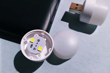
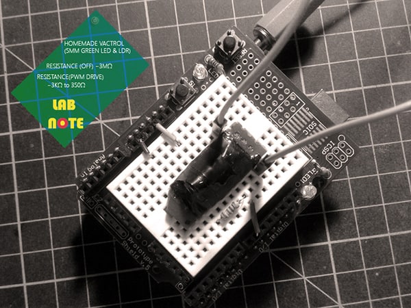
But now Vactrol is cheap – at least if you build it yourself. One LDR and one LED, and some heat-shrink tubing (or any other light-tight black shell) is all you need to build your own. I rigged up my own Vactrol with the most common 5mm LDR – GL5528, and a 5mm green LED. The peak spectral sensitivity of GL5528 is around 540nm, so I used that green LED but you can try other colors (from what I’ve tried the green and amber/golden yellow ones gave me the best outcomes). First, let’s look at its schematic and the quick layout idea for a small circuit board, you don’t need a devoted circuit board though!
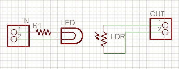
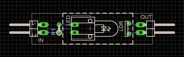
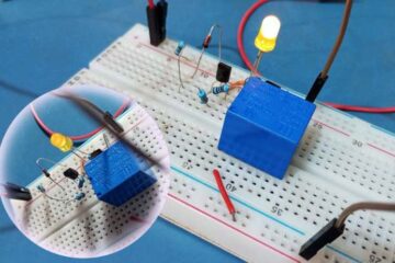
Simply get it done anyway you can but you should wrap the electronics in using anything that can make the assembly light-tight. Once I used a plastic tube for one that I got working on a perfboard but here I used another trick for my breadboard setup (you can see my build soon).
Homemade Vactrol & Quick Test
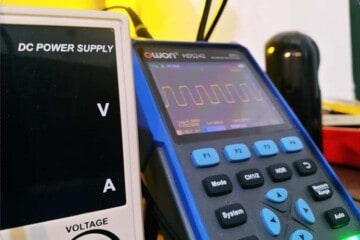
Still with me? Good, now see how to test your homemade Vactrols. The simplest method to test your Vactrol is to connect an Ohm meter across its output terminals (LDR). Then you can measure the resistance value in MΩ range if the Vactrol is fully light-proof. Next, apply regulated 5VDC to its input terminals (LED) through the series resistor (220Ω will be a decent value), and ensure that the output resistance value is in KΩ or Ω range. Done!
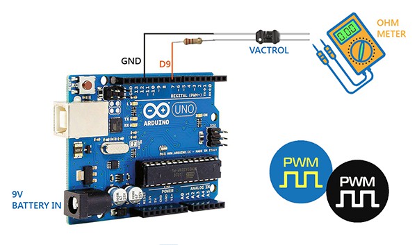
There is another – a bit luxurious – way to test Vactrols, by using an Arduino as a PWM signal generator. Here, the microcontroller is solely responsible for sending variable drive signals over time to the Vactrol. Since I already had a bunch of Arduino boards, I simply picked one Arduino Uno for the experiment. Of course, you’re free to use any microcontroller (and code), as there’re hundreds of variations to choose from.
An interesting thing about pulse width modulation (PWM) is that it does not render smooth linear analog type curves. But we can get smoothed curves out of pulse width modulation by stepping through values in a loop. I don’t want to discuss this now, so here’s what I came up with at first – just a crude code for testing Vactrols!
int x = 0;
const int pwmOut = 9;
void setup() {
  pinMode(pwmOut, OUTPUT);
}

void loop()
{
  for (x = 0; x < 128; x++)
  {
    analogWrite(pwmOut, x);
delay(1000);
  }
}
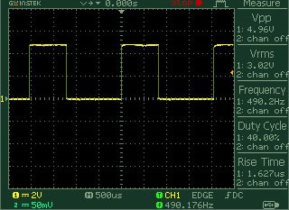
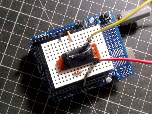
This is a random scope capture of the PWM output (generated by the above code) available through Arduino’s D9 pin. Here, the Vactrol can roughly ‘see’ a 0-50% duty cycle, 490Hz PWM drive signal at its input (LED). If you connect an Ohm meter across the output (LDR) of the Vactrol, you can assure that your ‘voltage-controlled resistor’ is in working order.
Recap: A Vactrol incorporates two discrete components merged into one lightproof package – a light-emitting diode, and a photoresistor. Feeding an appropriate voltage to the light-emitting diode causes current to pass through it and light to be emitted, which falls on the photoresistor. If a voltage is applied to the photoresistor, it will develop a current which is proportional to the voltage applied to the LED. This makes the setup, in effect, a voltage-controlled resistor.
Leaf the theory
It’s worth discussing a few common response-related features at this point. In order to get the maximum possible performance, the light source and photocell components in a Vactrol should have roughly equal wavelengths, which will require studying datasheets to find a good match. It usually doesn’t matter very much is there’s a small drift, but the closer you get, the more sensitive your Vactrol will be.
In principle, Vactrols are not high-speed devices as peed is limited by the response time of the photocell. With rise and fall times on the order of 2.5 to 1500msec, most have bandwidths between 1Hz and 200Hz (one of the characteristics of photocells is that their speed of response increases with increasing levels of illumination, thus the bandwidth is somewhat dependent upon the input drive level – the higher the input drive the wider the bandwidth).
And, naturally, the light output of an LED is proportional to the input drive current (IF). If we plot the transfer curve of output resistance versus input light current for a Vactrol we can usually see that it not only possess a large dynamic range, but the output resistance tracks the input current in a somewhat linear manner over a range of two or more decades.
Further, photocells exhibit a phenomenon knows as hysteresis, light memory, or light history effect. Special attention must be given to this characteristic because the photocell inside a Vactrol is normally in the dark. This will lead to having the photocell initially in a ‘dark adapted’ state in many conditions.
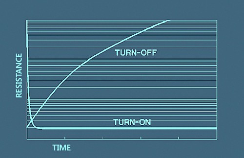
Oh, I overlooked that! Look, the turn-on and turn-off time of a photocell is not symmetrical. The turn-on time can be an order of magnitude faster than the turn-off time. In the dark, the resistance of the photocell is very high. When light is suddenly applied, the resistance drops rapidly, typically reaching 63% (1-1/e conductance) of its final values in under 10msec. When the light is removed, the resistance increases at an exponential rate initially, trebling in a few milliseconds and then increases linearly with time. This fast turn-on and slow turn-off responses (see below plot) can be employed to advantage particularly in audio applications.
So now we have a PWM/voltage controlled potentiometer. The next question is how to convert the resistance into a control voltage. To implement a potential divider with Vactrol, connect its first output terminal to a positive rail (5V-12V) through a resistor (1K-10K), and connect its second output terminal to ground rail (0V). Then use the midpoint as the ‘output’ terminal to deliver control voltage to an external circuit (or route the output to a microcontroller so that it can read and record output values). Hope you understand!
Next in line
Of course, a Vactrol on its own is pretty useless unless it is actually controlling something! There’re tons of circuits that use Vactrols on the internet, and I already tried many pretty big projects. But for you I thought I’d start fresh and create a new do it yourself hobby project may be powered by an Arduino microcontroller. Not sure if I will really exploit Vactrols for anything serious but it’s fun to build and play. Until next time, enjoy learning!
Credits & References