When a number of resistors are connected in such a way that the end of first resistor is connected to beginning of second resistor and the end of second one to third resistor and so on. We say that, resistors in series connection.
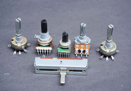
As you know, resistors are electronic components used to control voltage and current in circuit. But by correctly adjusting its value we can use it to control current or voltage in circuits and applications. Individual resistors can be connected together in either series or parallel connection to produce a valued resistor whose equivalent resistance is the mathematical combination of the individual resistors connected. All types of combination of resistors can be converted into an equivalent resistor no matter how complex that combination is because all the resistors follow the same rule i.e. the Ohm’s law.
What is Ohms Law?
Ohms law defines that, in any electric circuit the current passing through the components is directly proportional to the potential difference applied across the components. Ohms law exist in three forms. They are V=IR, I=V/R, and R=V/I.
Where R is the resistance, I is the current flowing in the circuit, V is the voltage. Based on these three parameters (current, voltage and resistance) ohms law states current changes directly with the applied voltage and changes inversely with the resistance.
Resistors in Series Circuit
A combination of series resistor circuit is arranged in a daisy chain fashion. Here current remains constant throughout the circuit. Once the current is passed to one resistor, it goes nowhere but straight to its destination i.e. negative terminal of the battery.
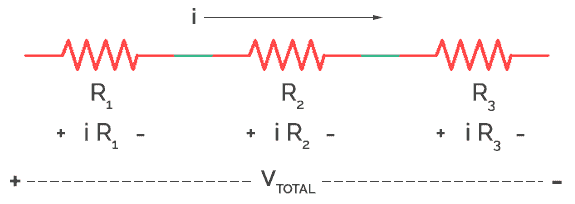
As the current here remains constant, current is the same throughout each resistor.
Therefore total current (i) in series circuit = i1 + i2 + i3
When we talk about voltage, it is divided in each resistor according to the value of resistors. But adding all of the individual voltage will result into total voltage in circuit.
V = V1 + V2 + V3
Now, according to Ohm’s law,
V = IR
∴ iR = iR1 + iR2 + iR3 + iR4
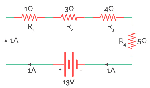
Therefore, the equivalent resistance of the above circuit (a) would be
R = R1 + R2 + R3 + R4
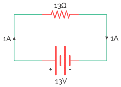
∴ R = 1Ω + 3Ω + 4Ω + 5Ω = 13Ω
Series Resistor as Voltage Divider
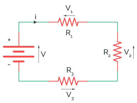
The entire voltage is divided into different voltage drops across each resistor as V1, V2, V3 and V4 and is calculated as
V1 (Voltage across resistor R1) = iR1 = 1 X 1 = 1V
V2 (Voltage across resistor R2) = iR2 = 3 X 1 = 3V
V3 (Voltage across resistor R4) = iR3 = 4 X 1 = 4V
V4 (Voltage across resistor R5) = iR4 = 5 X 1 = 5V
The total voltage is the sum of the voltages across individual resistances.
Therefore, V = V1 + V2 + V3 + V4 = 1V + 3V + 4V + 5V = 13V
The circuit (a) can be modified using a single resistor in series with a 1V battery.
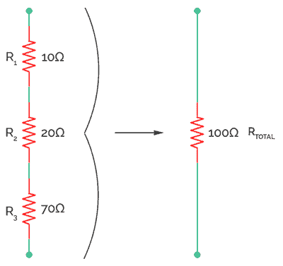
Thus this how resistors act in when they are connected in series combination. This type of combination is widely used when we need a big amount of resistance like 200Ω but 200Ω is not available in market so we connect two 100Ω resistors in series to get our required equivalent resistor.
Series Resistance Equation
Thus, equivalent resistance of these individual series resistors is just addition of their individual resistance. For example, if there are ‘n’ number of resistors say R1, R2, and R3 and so on up to Rn. The total resistance in series is given by the equation or formula below.
∴ Rtotal = R1 + R2 ± —— + … Rn
As far is battery is concerned several individual resistances are equal to one big resistance. This resistance or is known as Equivalent resistance.
The total resistance is given by = Total voltage/Total Current. It is obvious that this is the algebraic sum of individual resistors.
Resistor in Series Examples
To find resistance in series theoretically, here are example problems and solutions of resistor in series.
Example No 1:
To connect a resistor in series join one end of resistor R1 terminal with resistor R2 and R2 another end with R3. Likewise, you can connect ‘n’ number of resistors in series fashion shown below. This will increase the resistance.
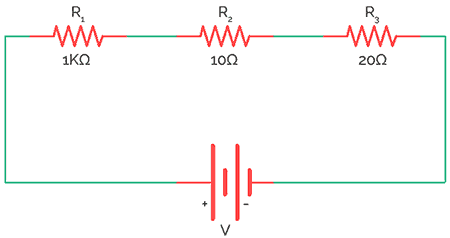
Here 3 resistors R1 (1K), R2 (10K), and R3 (20K) are connected in series. The total resistance in the circuit is given by the sum of resistances.
Hence, Total resistance (R) = R1 + R2+ R3+…..+Rn = 1K+10K+20K = 31K
Example No 2:
There will some situation where if you want to divide the voltage exactly into half. When two resistors of same values are series connected, the output voltage will become half of the input voltage. For example, two resistors R1 and R2 of same value 1K are connected one after another. The input voltage is 20V and output voltage is calculated as follows.
Here the load resistor (RL) not considered.
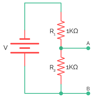
Without RL connected
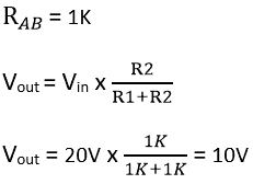
Hence, the series circuit divides the voltage and acts as voltage divider circuit.
Current vs. Series resistance
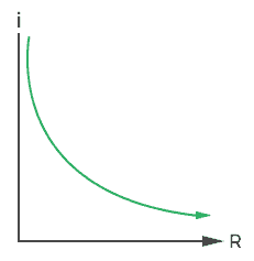
It is important to observe the relation between series resistance and current. As I said, resistor in series increase the resistance but decreases the current. Hence, the relation is inverse between current and resistance. Here as the resistance add up, the current decreases rapidly.
Applications
Some of the applications of series resistance in real life are
- Resistor in series are used to build voltage divider network.
- Used as thermistor (Positive temperature coefficient) in temperature measurement and control.
- Used as LDR (Light dependent resistor) for light sensing applications.