Voltage Divider and Current Divider are the most common rules applied in practical electronics. As you know, there are two types of combinations in a circuit, they are series and parallel connections. Parallel circuits are also known as current divider circuits because, in these circuits, the current is divided through each resistor. Whereas, series circuits are known as voltage divider circuits because here voltage is divided across all the resistors. Voltage division rule and current division rule are necessary to understand voltage and the current flowing through each resistor. These division rules are used in most common electronic devices.
Voltage Divider Circuit
In order to send a current through an electric conductor, an electromotive force has to be applied. When we say the current ‘I’ is passing flowing through the resistor ‘R,’ it logically follows that a force working across resistor R. This force is known as potential difference or voltage drop across resistor R. Similarly, if we consider any part of the electric circuit three quantities i.e. voltage, current and resistance comes together.
As we got to know that, a series circuit is known as a voltage divider circuit. It is a circuit which divides the voltage into small parts. So with a power source and two resistors, we can make an easy voltage divider circuit. Here we need to connect two resistors in series combination and then apply a voltage source across the series circuit.
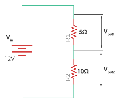
In this case, resistor R1 of 5 ohms and resistor R2 with 10 ohms resistance are connected. The voltages Vout1 and Vout2 are divided across the resistors R1 and R2. They can be calculated by a simple voltage dividing equation.
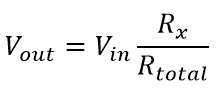
Where Rx is the resistor across which we need to find the voltage and Rtotal is the total resistance (R1+R2) in the circuit. It can be simply calculated by adding all of them as they are connected in series. Thus in the given circuit, the values of the voltage across each resistor are
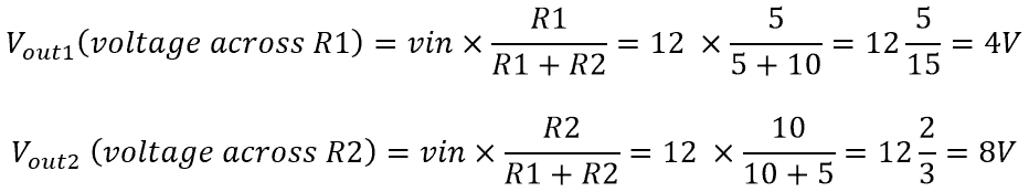
Therefore voltage across R1 is 4V and voltage across R2 is 8V. Thus here voltage is divided in the circuit across the resistors. Hence, this is called voltage divider circuit.
Voltage dividers are used in many applications but they are widely used in all types of variable resistors. Let’s take an example of a potentiometer. A potentiometer is a variable resistor which can be used to create an adjustable voltage divider. The potentiometer has three terminals two of the terminals are connected to the ends of the resistor and middle terminal is connected to the wiper. It has one resistance. The two outside pins are connected to the voltage source and the middle terminal acts as a voltage divider.
Current Divider Circuit
A current divider is a circuit which divides the current into small parts. As we got to know that parallel circuits are current divider circuit. So with a power source and two parallel resistors, we can make an easy current divider circuit. As in the current divider network, here we need to connect two resistors in parallel combination and then apply a current source across the parallel circuit.
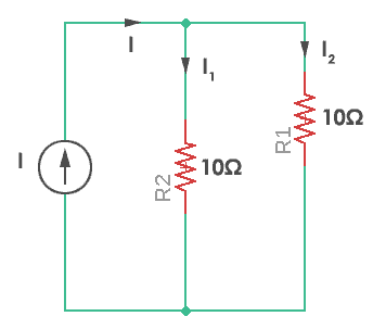
‘I1‘ and ‘I2‘ are the current divided across resistors R1 and R2. They can be calculated by a simple current dividing equation.
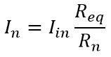
‘In‘ is the required current that flows through the resistor Rn. Req is the equivalent resistance of the parallel resistors.
Equivalent resistance (Req) is given by![]()
So, the current flowing through resistor R1 and R2 would be
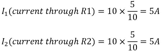
Here the resistors are of same value and so current will be divided in exactly half through each resistor. Thus this is known as the current divider circuit.
Almost every circuit we come across is either a voltage divider circuit, current divider circuit or it can be both of them. Voltage dividers are used in a variety of applications like variable resistors (potentiometer), LDR, thermistors and cutting-edge devices like an accelerometer. Current divider circuits are mainly used to simplify circuits that would make predictions of resistor selection easy.