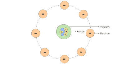
Electrical circuit is an interconnection of electrical components. An electrical circuit consists of batteries, resistors, inductors, capacitors, switches or transistors. An electrical network consists of a closed loop. A circuit is a closed path where electrons flow in a wire. As long as the copper wire is allowed to itself, the electrons drift between the atoms but never leave the copper.
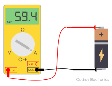
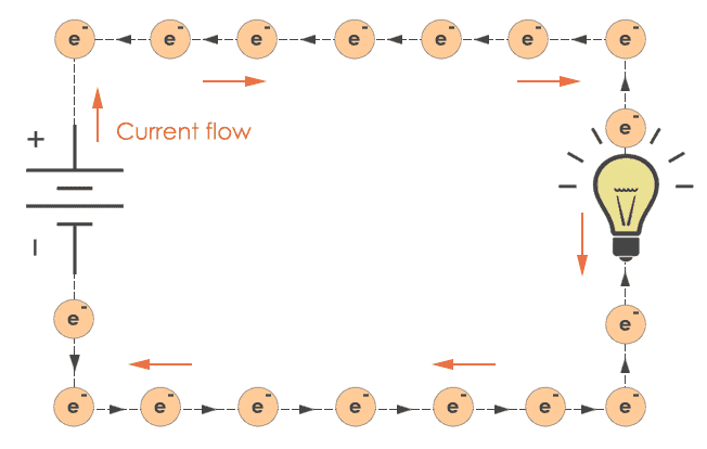
However, when we connect this copper wire to a battery the free electrons will be driven towards the positive terminal of the battery. This pushing force is called Electromotive force (E.M.F). The E.M.F. is expressed in volts. And usually, it is called voltage. As a result of this voltage, an electron motion takes place. This motion is known as electron current or electric current. We can measure current by connecting an ammeter between copper wire and voltage source.
A complete circuit is a never-ending loop of electrons. If we take a wire and loop it around, it forms a continuous path in which electrons can flow forever. This is a primary concept of a circuit.
An electric circuit mainly consists of
- Electrical sources that provide voltage and current like batteries. They are the source of electrons.
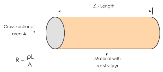
- Switches, resistors, potentiometers, capacitors which are used to control electricity.
- Protection devices in high voltage circuits. They are MCB, fuse, etc.
- Wires which are conducting path to carry electric current from one point to another in a circuit.
- Load in the circuit can be motor, LED, lamp, etc.
There are some basic properties of electrical circuits and they are:
- The circuit is always a closed path.
- A circuit always consists of an energy source,
- Direction of flow of current is from positive terminal to negative terminal of the source.
- Direction of flow of electrons is from negative terminal to positive terminal of the source.
Circuit Diagram
A circuit diagram is a visual display of an electrical circuit. There are mainly two types of circuit diagrams:
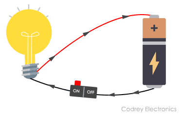
- Pictorial: Pictorial diagrams are made using basic images. This type of diagram gives a visual representation to audience which is less technical.
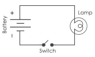
- Schematic: These diagrams are drawn using standard industrial symbols. These diagrams are used for the representation of a circuit to an electrician or any other technical audience.
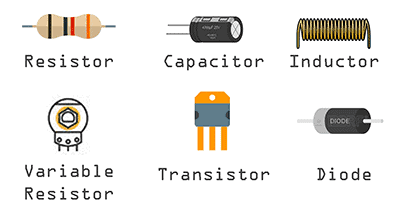
Circuit Diagram Symbols
There are hundreds of symbols for the circuit diagram. Some basic symbols are:
| Name | Symbol |
|---|---|
| Resistor | |
| Capacitor | |
| Cell | |
| Battery | |
| LED |
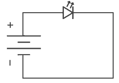
Suppose we want to draw a simple circuit in which battery is connected to LED in such a way that positive terminal of the battery is connected to positive terminal of LED and negative terminal of the battery is connected to negative terminal of LED. Then it can be represented as:
Types of Circuits
There are basically three types of circuits:
-
Open circuit
If in a simple circuit one terminal is disconnected, then there is no flow of current through that circuit. This is said to be an open circuit or no load condition.
-
Closed circuit
An electric circuit has a source of Electromotive force and a load. This load acts as a conductor path. If the current flows through the load it is considered as a closed circuit. If in a simple circuit, current can flow from one terminal of the battery to another without any discontinuation is said to be closed circuit.
-
Short circuit
If the positive terminal of the battery is directly connected to the negative terminal without any resistance between them is said to be a short circuit.
Other than the above circuits, components in an electric circuit can be arranged in two different ways and that are in series connection and in parallel connection.
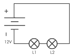
Series Circuit
If in a circuit, components are connected in series then the circuit is known as a series circuit. In a series circuit, current through each component is same and voltage supplied is the sum of the voltage across each component. If a wire joins the battery to one lamp, to the next lamp and then back to the battery, the lamps are said to be connected in series.
Parallel Circuit
If in a circuit, components are connected in parallel then the circuit is known as parallel circuit. In a parallel circuit, the voltage across each component will be same and total current applied is the sum of current through each component. If a lamp is connected to the battery and another lamp is connected in a separate loop with first lamp, then lamp is connected in parallel connection.
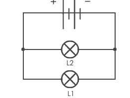
Here, the voltage across each bulb would be the same as the voltage applied by the battery. Current across each lamp would be divided means if we appply 5A to the circuit, 5A will be the current flowing through each lamp.
Thus this is how series and parallel circuits work and they have their own current and voltage dividing properties.
Electric circuits are all around us, in our mobile phones, in our computers, in fan and also in the torch. It is difficult to assume the practical use of electricity without circuits. We are all dependent on these complex circuits around us.
Its information is very most important.this is always help of students and teachers thanks you so much google but you are most to be all the world .love you.
thank you
Applied electricity student and I love your teachings