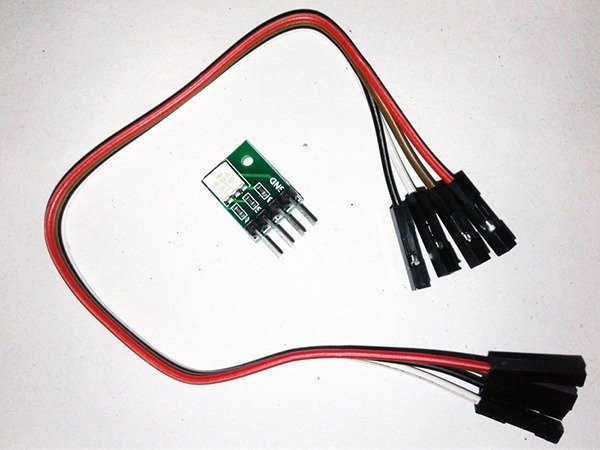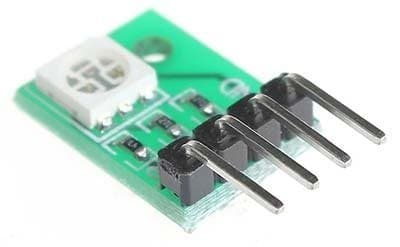
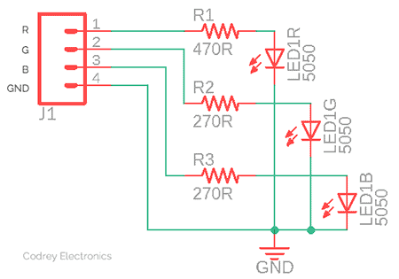
The RGB LED module shown in the above image is a very popular generic RGB LED module available in the market. There are mainly two variants of this module having common-cathode (CC) and common-anode (CA) configurations. The most usual is the common-cathode RGB LED module with a single SMD5050 RGB LED and three current limiter resistors. You can see the module’s circuit diagram (drawn by me) below.
This small LED module, unlike the fantastic Neopixel LEDs, can simply be run through an Arduino (or Attiny85) microcontroller without using any special third-party libraries. So it’s easy to build your own fancy lights, festival light, mood lights, signal lights etc. apparently requiring less effort. It would be good to start the experiment with a pretty crude code which resides in Arduino and controls the LED module. As mentioned, the experimental code does not include a library. Concerning the hardware setup, one nice option would be to put the LED module on the Arduino header upright. At this point it is worth noting the ‘soft’ connection trick – one I/O is used as the GND of the LED module!
/*
 * RGB LED MODULE (CC)
 * QUICK TEST CODE
 * R=D9/G=D10/B=D11/GND=D12
 * T.K.Hareendran/2019
 * https://www.Codrey.com/author/tkhareendran
 */
#define RED_LED_DIO 9
#define GREEN_LED_DIO 10
#define BLUE_LED_DIO 11
#define GND_LED_DIO 12 // LED GND (0V)
void setup()
{
  pinMode(BLUE_LED_DIO, OUTPUT);
  pinMode(RED_LED_DIO, OUTPUT);
  pinMode(GREEN_LED_DIO, OUTPUT);
  pinMode(GND_LED_DIO,OUTPUT);
  digitalWrite(GND_LED_DIO,LOW);
}
void loop()
{
  int k;
 for (k = 0; k <=255; k++)
  {
    analogWrite(RED_LED_DIO,255 - k);
    analogWrite(GREEN_LED_DIO, k);
    delay(10);
  }
  for (k = 0; k <=255; k++)
  {
    analogWrite(GREEN_LED_DIO,255 - k);
    analogWrite(BLUE_LED_DIO, k);
    delay(10);
 }
  for (k = 0; k <=255; k++)
  {
    analogWrite(BLUE_LED_DIO,255 - k);
    analogWrite(RED_LED_DIO, k);
    delay(10);
  }
}
The ATmega328P chip in Arduino Uno has three PWM timers (Timer 0, Timer 1, and Timer 2), controlling 6 PWM outputs. Each timer has two output compare registers that control the PWM width for the timer’s two outputs. The two outputs for each timer will normally have the same frequency, but can have different duty cycle. The above code uses simple pulse width modulation (PWM) with analogWrite by simply call “analogWrite(pin, duty cycle)” where pin is one of the PWM pins (3,9,10,11,5,6) and duty cycle is a value from 0-255 (must be in the range 0 <= level <= 255). Remember that the default PWM frequency of Arduino UNO PWM output is actually 490.196Hz or 976.5625Hz simply depends on the PWM pin number used by default. A more elaborate description on Arduino pulse width modulation is available here http://www.arduino.cc/en/Tutorial/PWM
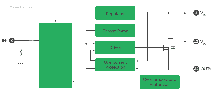
Single I/O of an Arduino Uno can sink or source maximum current of 40mA, but in practice it’d be safe to limit that to 2omA per I/O. A single RGB LED module never needs more than that so there’s nothing to worry about. Obviously, usage of multiple modules calls for appropriate power driver circuits built with either transistors or ICs. For the power driver, you can use one suitable bipolar transistor or power mosfet per channel but now I would like to suggest a mosfet array for that job as it is a very compact solution. Recently I found an 8-channel high-side power switch array IC from Toshiba, good for lamp drivers too. Part number of the TTL-compatible 8-channel power IC is TPD2005F available in SSOP-24 package (6-channel output is enough for two LED modules). Below you can see its single channel block diagram.
Just to fend off an overkill, you can try the little Digispark board for playing with RGB LED modules rather than perverting the big Arduino. Digispark has PWM on 3 pins – P0,P1,and P4 (more possible with Software PWM), and the GPIO output is 20 mA max per pin. More detailed info here: http://digistump.com/wiki/digispark/tutorials/basics. Given below is a quick play code prepared for Digispark.
#define redLED 0 // LED Module Pin 1 (R)
#define greenLED 1 // LED Module Pin 2 (G)
#define blueLED 2 // LED Module Pin 3 (B)
#define gndLED 4 //LED Module Pin 4 (GND) – See Note!

void setup()
{
pinMode(redLED, OUTPUT);
pinMode(greenLED, OUTPUT);
pinMode(blueLED, OUTPUT);
pinMode(gndLED, OUTPUT);

digitalWrite(redLED, LOW);
digitalWrite(greenLED, LOW);
digitalWrite(blueLED, LOW);
digitalWrite(gndLED, LOW);

delay(500);

}

void loop()
{
digitalWrite(redLED, HIGH);
delay(500);
digitalWrite(redLED, LOW);
digitalWrite(greenLED, HIGH);
delay(500);
digitalWrite(greenLED, LOW);
digitalWrite(blueLED, HIGH);
delay(500);
digitalWrite(blueLED, LOW);
}
Take note, P3 and P4 of Digispark are used for USB communication and programming, while you can use them in your circuit if you are not using USB communication. So you have to detach the LED module wires during programming as it may affect the voltage levels on the pins, otherwise. Besides P3 has a 1.5 KΩ pull-up resistor attached to it which is mandatory for when P3 and P4 are used for USB communication (and programming) so it is necessary to overpower this to pull P3 low. That’s why P4 (not P3) is used as the common GND lead of the LED module. Else you can tie common GND connection of the LED module to GND point of Digispark (leave P4 as is). However, in both cases you should wire up the RGB LED module externally using jumper wires as direct mounting on Digispark I/O header is not very comfortable (if you build a special shield, it will).
Without a Microcontroller?
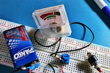
Yes, it might be possible to drive this RGB LED module without any microcontroller. For that what you need is a cheap presettable CMOs up/down counter and an adjustable clock source. See this DIY idea (for common-anode LEDs) with CD4029 IC and a few other simple parts https://www.electroschematics.com/12218/laymans-rgb-led-module/
According to datasheets, CD4029BE (in 16-pin DIP) is a ‘multifunction’ chip i.e. it consists of a four-stage binary or BCD-decade up/ down counter with provisions for look-ahead carry in both counting modes. So you can create simple LED light effects and/or rainbow light effect if tailored in the right way. The IC will work up to 20V DC supply voltage, and meets all requirements of JEDEC Tentative Standards No. 13B, “Standard Specifications for Description of “B” Series CMOS Device’s.
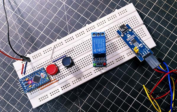
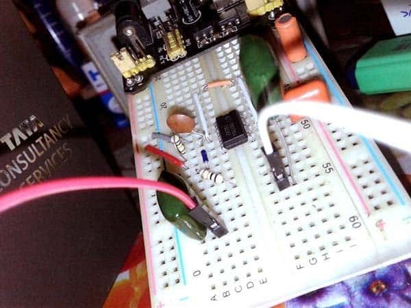
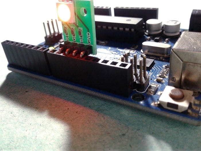
Now look at the casual snap of my Arduino experiments. Also watch the quick video footage.
Finally a word about my RGB LED Module. Rather unsurprisingly, the unit came in a zip-lock anti-static ESD shielding bag and that was it. Inside the packet there’s also a good-quality female to female (x4) jumper cable (see last figure). While testing the module with a regulated 5V dc power supply, I observed that the red one consumed about 6.5mA while consumption of the green and blue was 7.5mA per branch. This registers 21.5mA of total current consumption at 100% brightness!