Every electronics hobbyist’s lab, or green energy lover’s home, needs an outdoor light powered by solar. If you’re one of them you should probably consider building this super simple mini solar street light for you!
Circuit Diagram
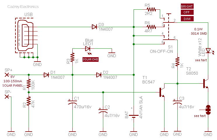
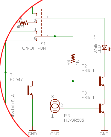
Circuit Description: The circuit is designed to work with a small 6V (100mA-150mA/250mA) solar panel (SP) for charging the built-in 4V/1Ah sealed lead-acid (SLA) battery. One blue indicator (LED1) notifies the status of the solar charging process. It’s noteworthy that the battery can also be charged through a USB power supply in an emergency situation when ample sunlight is absent or unavailable.
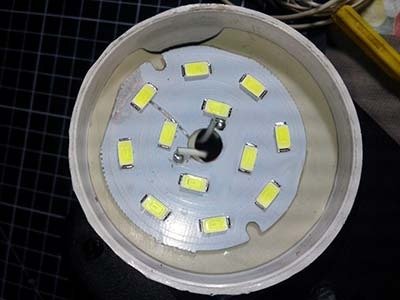
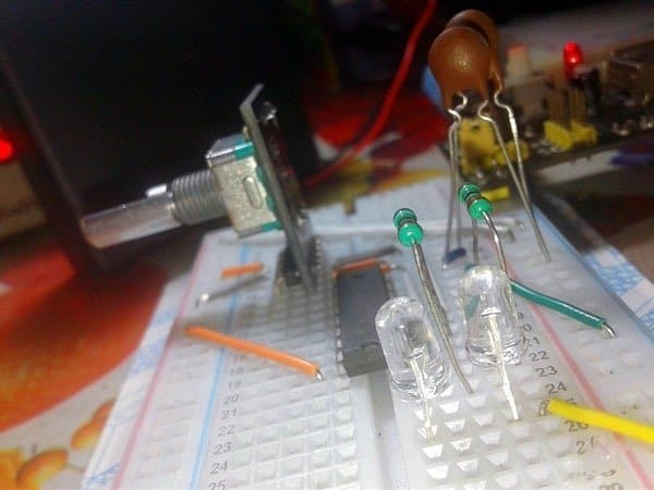
Light source in this circuit is a bunch of twelve parallel-connected white LEDs driven by a medium-power transistor S8050 (T2). In the proto model, SMD type 3014 warm-white LEDs mounted on a circular aluminum heat sink (placed inside a cheap LED bulb enclosure) was used to ensure a touch of beauty (see below image). Technically, the single 3014 LED used here has a typical forward voltage (Vf) of 3.3V at 30mA forward current (If), resulted in 100mW power. Thus total power of the LED cluster is near to 1.2W but it’s slightly under driven here deliberately, even in the bright mode.
There’re two current-limiter resistors for the LED cluster which can be selected through the 3-way (on-off-on) DPDT rotary power switch (S1). The 2R2 resistor (R5) is for ‘bright’ mode while the 4R7 resistor (R6) sets the LED current in ‘dim’ mode. First BC547 transistor (T1) is used to switch the LED driver transistor T2 only in nighttime. Resistors R1-R2 determines the switching threshold of T1 as its connected across the output of the solar panel. Usually, when the ambient light level is less than 10 lux, T1 fires T2 and hence the LED cluster. Finally, the 470uF electrolytic capacitor (C1) is a ‘buffer’ for the solar panel while next two capacitors (C2-C3) merely keep the system stable i.e. without any fluctuation.
Add On: The 3-way solder jumper between T2’s emitter and ground rail is added for the inclusion of a passive infrared (PIR) motion sensor, if desired. With such a human-motion detector, the light source turns on for a finite time only after the detection of a valid human-motion thus saves battery power to a great extent and naturally gives more run time. However that’s not very easy here because of a few technical reasons.
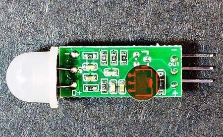
Typical Vcc of the circuit is only 4V from the SLA battery therefore the common HC-SR501 PIR motion sensor module can’t be used here. Because HC-SR501 requires a minimum dc input of 5V, it can be ‘hacked’ for 3.3V operation though. A workable solution is the use of the new mini PIR motion sensor module HC-SR505 (see next image). The HC-SR505 appeared to be ideal because it is would not waste much space on the enclosure and its electronics is much simpler than that used for the HC-SR501.
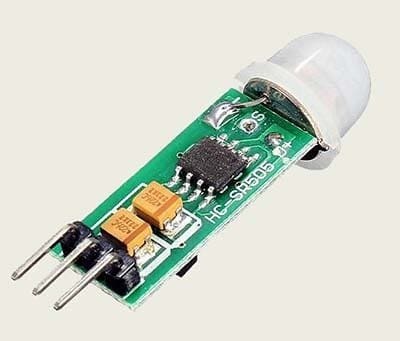
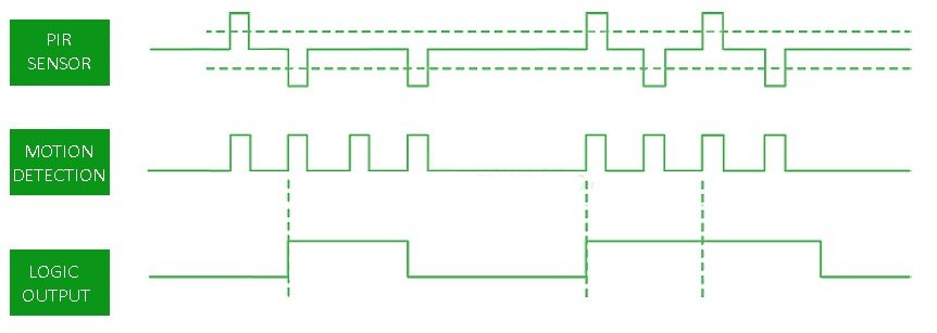
The HC-SR505 module has an onboard 3.3V LDO voltage regulator (HT7133-1) that accepts dc input from 4.5V to 20V. At the core of the module is one 8-pin PIR sensor controller EG4001. Default trigger mode of the module is ‘retriggerable’ mode that means the module will continue to output a logic-high signal as long as it continues to detect movement as depicted below.
You can try one HC-SR505 module in this circuit by adding one more S8050 transistor (T3) as indicated in the next example schematic.
Best position for mounting the PIR sensor module is the same side of the enclosure reserved for the LED bulb i.e. bottom panel. Rarely, the available 4V is inadequate for running HC-SR 505. If so, do a little more tryouts by replacing its onboard HT7133-1 with another 3V LDO voltage regulator HT7530-1 available in similar SOT-89 package (see below).
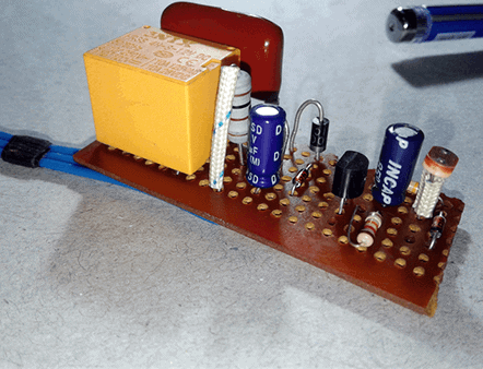
& The photo of my finished prototype in working order. Note that the ‘hat’ you can see near the solar panel is not a motion sensor – it’s just a vacant slot reserved for future to mount an error indicator or similar annunciators.

Theory is nice but in practice not everything is accurate, even if it is accurate, the results sometimes will not be satisfying. So make this pretty simple circuit yourself, test it in real-world, and remember to share your thoughts here. Happy Soldering!

Great circuit. please for more explanation on the role of the capacitors. what is meant by C1 is a buffer for the solar panel? what is the advantage of the capacitors?
thanks
Ngang
@Ngang: In a solar powered device the energy of the solar energy can either be
used directly or can be used to recharge a battery pack which in turn can power the application electronics.
What’s important then is a “smooth” energy transfer, that is, on one side from the solar panel into the rechargeable battery and on the other from the battery towards the energy consuming application.
In this circuit, the energy of the solar (photovoltaic) cell is first stored in the buffer capacitor C1 (buffer is just the name of what it is doing, it is just a capacitor) and then routed into the battery pack. In other words, it means C1, not harmful at anytime, acts as a simple “reservoir” for farther connected circuits.
Finally, in the general sense, a buffer is something that serves as a protective barrier. Read this note – https://yourbusiness.azcentral.com/buffer-electronics-20738.html
Thanks!