Toy DC Motors, also known as Hobby DC Motors, can be a good choice for low-budget or pocket-friendly basic electronics projects. They are very rugged, easy to use, and generally available with a wide range of voltage levels. Moreover, these motors can rotate in both directions and speed governing is also possible.
While these dirt cheap and ubiquitous motors, unlike their more muscular cousins, have their own set of challenges to play with, there are many good reasons to get familiar with them. So, let us get started now!
First off note that toy motors are simple two-lead dc brushed motors. If you are not familiar with the workings of a toy motor, it is better to go through this great write-up https://theengineeringmindset.com/dc-motor-explained/.
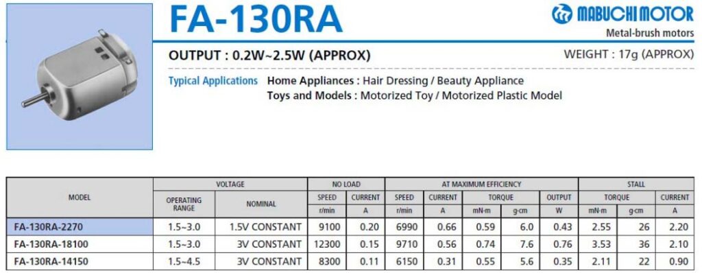
The first thing to note is that most of the toy motors are made by or are made to imitate motors from the Mabuchi Motor Corporation of Japan. And they usually come with an operating voltage range of 1.5V to 4.5V DC. In the datasheets, you will find things like voltage, running speed, stall current, stall torque, etc. Below is a snip of the toy motor datasheet from Mabuchi (https://www.mabuchi-motor.com/).
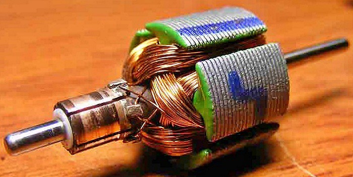
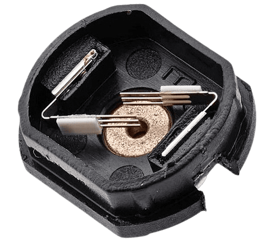
And, at least as I understand it, most of these toy motors do not have the carbon brushes but have a slip of copper that has been stamped to have a few slim fingers pressing against the commutator (see below). That is why it is referred to as a metal-brush motor in the datasheets.
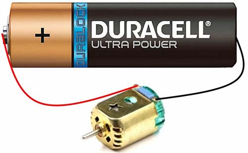
Touching on the simple toy motor driving tricks, a single 1.5V AA battery (https://en.wikipedia.org/wiki/AA_battery) is all that is needed for a quick run. In order to make it rotate just connect the positive (+) side of the battery to one terminal and the negative (-) side of the battery to the other terminal and you should see the motor rotating. If you want to reverse the rotation of the motor simply interchange the terminals and direction will also be reversed.
At this point, note that the toy motor consumes 200mA of current even under no-load conditions, which will jump manyfold with a load, so make sure your power source can cater it.
In order to control the speed of the toy motor you need to vary the voltage supplied to it and there are many (simple and complex) ways to achieve that. If you are using a microcontroller for that, an all-purpose simplex dc motor driver circuit similar to the one shown below is mandatory in every case.
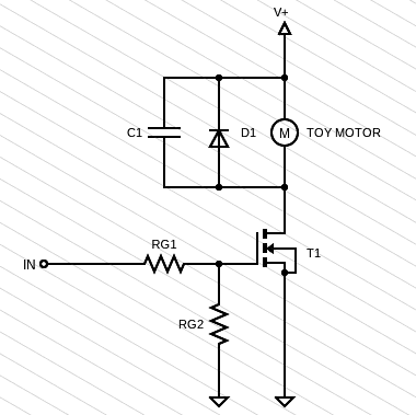
As can be seen from the above schematic, an N-channel Power MOSFET (T1) is used as a low-side switch to drive the toy motor. This component should be a “logic-level” type so the commonly available IRL520 (or IRLZ44) MOSFET can be used here.
Now you can turn the toy motor (M) on and off by switching the input (IN) HIGH and LOW. And by using pulse width modulation (PWM) on the input, you can also govern the speed of the toy motor.
Looking at other components, the flyback diode (D1) wired in parallel with the toy motor wipes out the potential drain-source overshoots that occur when the motor’s inductance dumps its current back to the circuit when the MOSFET is switched off. The ubiquitous 1N4007 diode is a good choice for this application.
Likewise, the toy motor will certainly inject noise spikes into the circuit. The capacitor (C1) across the toy motor will help stamp down it to some extent. A 100nF (0.1uF) ceramic capacitor would be a good pick here.
The gate of the MOSFET turns like a small capacitor that starts charging when a voltage is applied, so the first gate resistor (RG1) is there to limit the current from the I/O of the microcontroller. Note, that initial current draw may be too high for the digital I/O pin of most microcontrollers.
Similarly, the second gate resistor (RG2) is used to pull down the gate of the MOSFET to ensure a predefined state when there is no drive command at the input (undefined gate potential).
According to my rough calculation, the ideal values here are 100Ω to 220Ω for RG1 and 10 KΩ to 47KΩ for RG2. But for more prominent projects, you should focus more on the selection of these gate resistors.
At last, to the fun part…
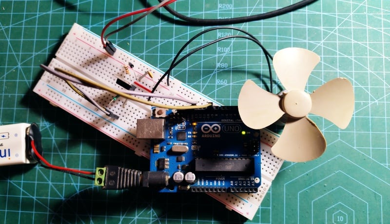
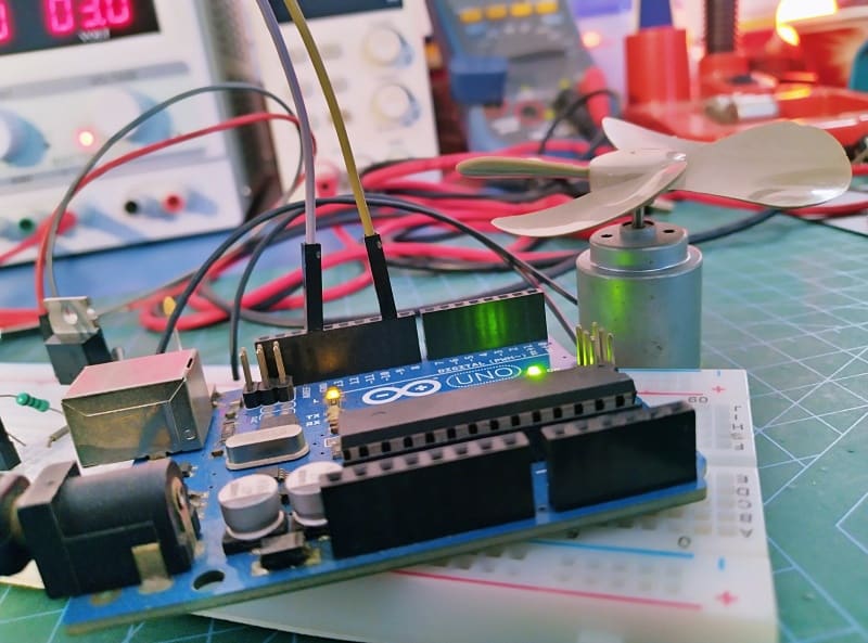
Well, I decided I would not stop here. Now that I have the power driver circuit for the toy motor, I thought I would try to use it with an Arduino. I achieved this by making a simple code to run the toy motor in an unusual fashion. The code is as follows.
const int drivePin = 9;

void setup()
{
  pinMode(drivePin, OUTPUT);
  delay(3000);
}

void loop()
{
  driveAcceleration();
}

void driveAcceleration()
{
  int speed;
  int detainTime = 10;
  for (speed = 0; speed <= 255; speed++)
  {
    analogWrite(drivePin, speed);
    delay(detainTime);
  }
  for (speed = 255; speed >= 0; speed--)
  {
    analogWrite(drivePin, speed);
    delay(detainTime);
  }
}
It is just a fun program to progressively accelerate and decelerate the toy motor back and forth endlessly. The input to the toy motor driver is provided by the D9 pin of the Arduino Uno powered by a 6F22 9V battery and uses a separate 3VDC power supply for the toy motor (the ground rail is common to the entire setup).
Of course this is a whimsical application just for fun. But I might exploit this idea to mod a motorized toy later. I think it would be a wonderful thing especially for kids. Let us see!


Nice article.
In this circuit and others, how does one calculate what type of a Capacitor, and their values, and resistor values to be placed in the circuit.
e.g: You have a .1uF Ceramic Capacitor – How was it determined that this capacitor had to be used ?
Also, why not a transistor instead of a Mosfet.
Enjoyed the article.
Thanks @Shashi Kiran!
Most of the time I include key design maths in my articles but it is not always possible due to many factors like space paucity and time constraints. But sooner or later I will start a series here which may help readers to design their own circuits better. Stay tuned!