This post demonstrates an example of a cheap ceramic resonator based 500kHz oscillator.
You can consider this a more practical version of my previous post on this topic Learn To Play with Ceramic Resonators
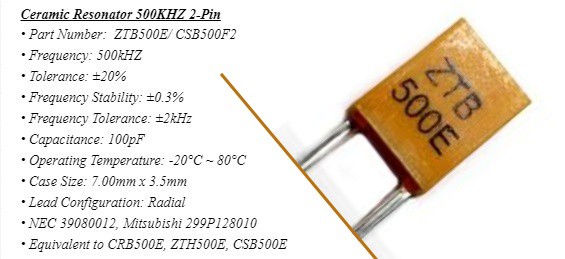
The ceramic resonator part used here is an equivalent of the ZTB500E, specified to resonate at 500kHz. I am using two gates of the MC14069UB unbuffered CMOS hex inverter chip as inverters to drive the ceramic resonator in my circuit.
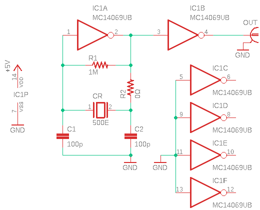
Here is its tried and tested schematic:
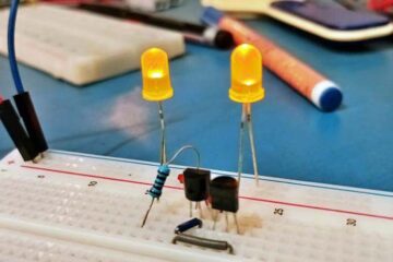
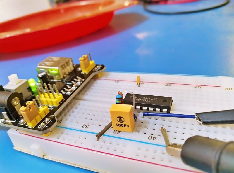
Now see how I wired it on a breadboard. As usual, regulated 5VDC provided by the breadboard power supply module was used for testing the prototype. It worked!
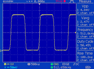
This is the output waveform as captured by my oscilloscope (x10 probe):
My original intention was to build a poor man’s 500kHz oscillator with no particularly high tolerances or precision. This is purely for testing purposes, so small drifts in duty cycle and/or frequency are not a big issue (in my case).
Note that the most common oscillator circuit for a ceramic resonator is the Colpitts’s Oscillator circuit. The circuit presented here is in fact a basic oscillator circuit with two invertor gates. The first gate (IC1A) works as an inverting amplifier for the oscillator circuit whereas the second gate (IC1B) acts as a waveform shaper and buffer for the output.
The 1MΩ feedback resistor (R1) provides feedback around the inverter so that the oscillation will begin when power is applied. The role of the damping resistor (R2) is to make the coupling between the inverter and the feedback circuit loose, thereby minimizing the load on the output side of the inverter. The damping resistor is omitted as it is not very critical in this circuit, so use a 0Ω jumper there.
The 100pF ceramic capacitors (C1-C2) are there to introduce a 180° phase lag. These loading capacitors should be properly picked out depending on the application, as the oscillation frequency is influenced by the value of the loading capacitors.
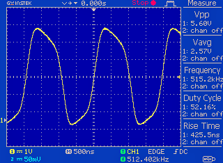
And, this is the “sine-wavish” signal appears at the output (Pin 2) of the first inverter gate (IC1A):
The ceramic resonator in this particular circuit is somewhat replaceable, which means you can use standard ceramic resonators in the 430-699kHz range without changing any other circuit components. I did a second successful experiment using the more common 455kHz ceramic resonator (CRB455E) fetched from an old television remote control handset.
Then, the oscillation frequencies will be almost identical to the marked resonance frequency of the ceramic resonators. However, you will get a much happier result when switching from the breadboard to a properly designed PCB.
That is it for now! Anyway, I still keep my breadboard build intact as I want to do a few more experiments just to quench my thirst (story for another day).
Next in this series are some design ideas for making ceramic filter (https://www.argotech.com.tw/dip-ceramic-filter.html) based oscillators. Stay in the know!