Once again, the design concept of an Eternal LED Blinker configured to operate from a DC supply in the 3V to 12V range and consisting of only a few components. Since its power consumption is practically negligible, it is suitable for long-term battery-powered operation.
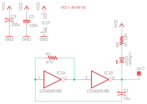
Let us start with its circuit diagram. Keep note at this point, depending on the values of the timing components, the blinking rate changes, which is about 1Hz by default. There are numerous potential applications for this circuit, nothing going to stop you except your imagination!
Component List
- R1: 47KΩ ¼ w Carbon/MFR
- R2: 1KΩ – 10KΩ ¼ w Carbon/MFR (see note)
- C1: 10uF/25v Electrolytic
- C2: 100nF (0.1uF) Ceramic
- C3: 100uF/25v Electrolytic
- LED1: Red or Green 3mm/5mm (Low Current Type)
- IC1: CD4049UBE (TI)
This project is based on the commonly available (but a bit old) hex inverting buffer and converter IC – the CD4049UBE (IC1).
First off, notice that the unused input pins of IC1 must not be left unconnected because the undefined voltages at the outside connections result in undefined operational states. So, all unused input pins (7-9-11-14) must be connected to VCC or GND rail to prevent them from floating (this is not shown in the schematic given above). Also, the 100nF bypass capacitor C2 must be wired as close to the Pin 1 of IC1 as possible for best results.
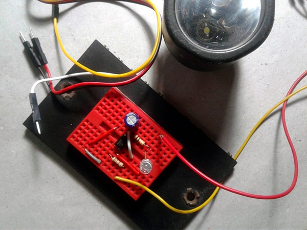
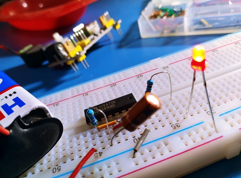
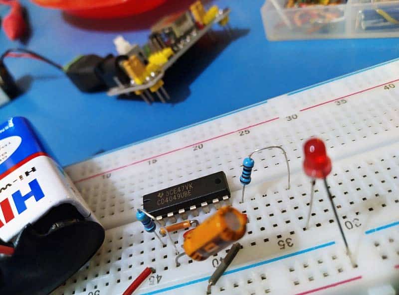
Similarly, the value of the LED1 series resistor (R2) needs to be changed according to the actual operating voltage. You can start with 1KΩ (for 3-5V), 2K2 or 4K7Ω (for 9V) or go up to 10KΩ if low luminance is not an issue. Most of my breadboard experiments were with a 10KΩ resistor and a cheapo 9V battery (see below).
The CD4049UB datasheet says it has a relatively high sink current, so LED1 is wired to take advantage of that feature. The output current, however, is very limited, so where the output current is significant, a buffer must be added.
And, as mentioned before, depending on the values of the R-C timing components (R1-C1), the blinking rate changes by nature. According to my frequency counter, the default output frequency is close to 1.1Hz (yours may vary slightly, no matter).
So, the circuit provides a variable clock frequency good for many applications, all that needed is to carefully take the R-C timing components. Formula to calculate the approximate output frequency FOUT is 1/1.39 x R1 xC1, where R1 is in KΩ, C1 is in uF, and FOUT is in kHz.
For a better understanding of the functionality of the IC you will need to go through the revised CD4049UBE datasheet published by Texas Instruments.
Also see this related do it yourself project: https://www.codrey.com/electronic-circuits/cmos-toggle-switch-with-cd4049/

Alright, it is not that bad. So do not ever think that you are wasting some time playing with an LED blinker circuit when dirt-cheap flashing LEDs are readily available these days. As explained many times on this site, building an LED blinker is one of the first lessons in basic electronics because you can always learn something new when you build it with discrete parts. While I have to admit it can be a little difficult, figuring out exactly how to turn an idea into a functional aspect can be an invaluable learning experience. Have Fun!