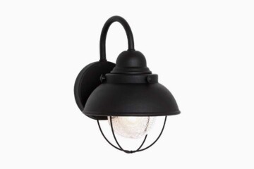
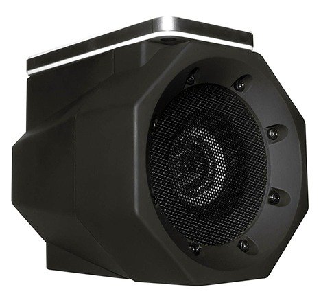
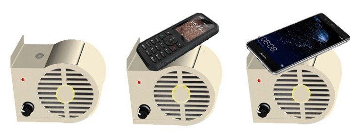
Back a few months I got one Boom Touch Wireless Portable Speaker from a friend abroad. Boom Touch is a compact speaker which amplifies audio signals without cables or Bluetooth. The Boom Touch uses inductive audio coupling technology (sometimes called as near field audio technology), so when you simply place your mobile phone on its flat-topped dock, the audio from the mobile device is amplified through the Boom Touch speaker. A pretty nifty Boombox!
Naturally I was quite inspired in a flash, and wanted to make something similar to the design. Anyway, I couldn’t find reliable design ideas/application notes for making such mysterious speakers based on inductive audio coupling technology, thus I halted the serious experiments and simply got down developing a variant of the same concept. This article will show you how to build a poor man’s edition of the Wireless Mini Boombox using inexpensive and easily available electronic components.
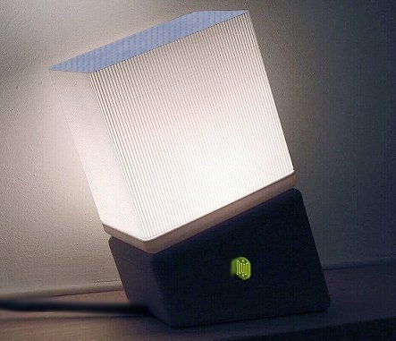
Poor man’s Wireless Boombox
Even though the presented design is a ‘gimmick’ adaption, it’ll work as a true wireless speaker and produce crystal clear sound output. The battery-powered wireless speaker, suitable for outdoor entertaining or rocking out at home, also gives a significant boost to the audio coming out from your mobile phone (or any portable music player with an external speaker) placed on the top of the enclosure.
Off the wire
This part goes to the circuit diagram of the Wireless Mini Boombox. First, it’s worthy to note that the ‘wireless’ technique used here is merely a cheap form of the good old ‘acoustic coupling’ method realized with the help of a common electret condenser microphone (ECM). Description that directly follows the schematic will give you a clear idea of the construct.
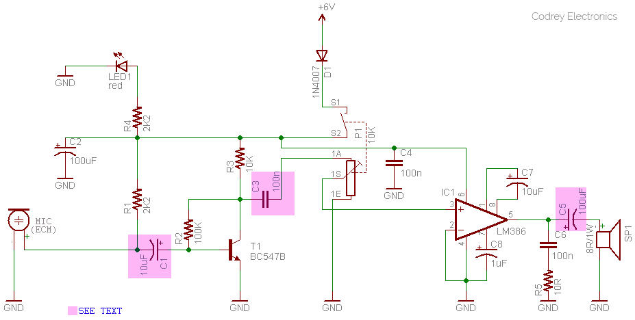
Since the circuit runs on 6VDC supply, a series combination of four 1.5V AA/AAA dry cells will be a good power source for a moderately long run. The 1N4007 diode (D1) is a simple reverse input polarity protector. Note that the power on/off switch (S1-S2) is an integral part of the 10K volume control potentiometer (P1). The red light emitting diode (LED1) works as the ‘power on’ indicator.
Frontend of the circuit is ofcourse the electret condenser microphone (ECM) usually called as condenser mic or button mic. The unidirectional microphone used here is a type from CUI INC® (www.cui.com) – Part number: CME-1538-100LB. A 2K2 resistor (R1) is used as its load resistor (Anyway you can experiment with resistor values from 1K to 10K).
The ECM preamplifier is a close replica of the ‘textbook’ circuit. Key part of the preamplifier is a BC547B transistor (T1) with self-stabilizing bias current mechanism. The input and output ac-coupling capacitors are C1 and C3 respectively (Suggested values for both capacitors are from 100nF to 10uF).
The final power amplifier part is built around the omnipresent tiny audio power amplifier chip LM386 (IC1) designed for use in low voltage consumer applications. Here, the LM386 is wired as a more versatile audio power amplifier with gain 200. The typical output power is about 325mW on the 8Ω loudspeaker (SP1). Signal output from IC1 is fed to the loudspeaker through the 100uF coupling capacitor (C5).The Zobel Network comprised of C6(100nF) and R5(10Ω) puts up a ‘load’ for high frequency components of the amplified signal and crushes potential high frequency oscillations. A 220uF or 250uF electrolytic capacitor can also be tried instead of the 100uF (C5) coupling capacitor. Refer the official LM386 IC datasheet to get more ideas on application and implementation.
The small condenser microphone is used for converting acoustical energy (sound) into electrical energy. It’s more sensitive and have greater dynamic range than similar dynamic microphones. Operating voltage of the microphone is 2V typical (10V max), and its frequency range is 20Hz – 20kHz (Sensitivity -38dB ± 3dB). Output of the microphone is first fed to the preamplifier to boost the signal level, and then a power amplifier is used to boost the pre-processed signal level further to drive the loud speaker. Series ac coupling capacitor with a value of 100nF-10uF is used at the input and output of the microphone preamplifier. As observed, the little microphone is able to capture nearby sound signals well within 50mm range (omnidirectional) that’s enough for the proposed application, and thus provides a simple way to pick up, amplify, and reproduce audio signals delivered by the loudspeaker of a mobile phone/music player within its close proximity!
It’d be more well to assemble the microphone preamplifier on a small piece of veroboard, and the power amplifier on another one (total two interconnected circuit boards). The component layout is not very critical but ensure to keep the length of wires/copper tracks as short as possible. It’s recommended to place the 100nF capacitor (C4) close to the LM386 (IC1) power supply pins (6 and 4).
Enclosure preparation
Enclosure preparation is the most trickiest part of the construction! If you gain access to a 3D Printer, then go for a 3DP enclosure, else try to build it with wood or acrylic boards (refer the enclosure outline below).
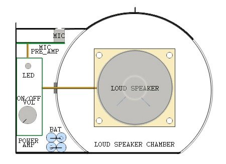
Remember to mount the microphone on the underside of the slightly curved top panel. All you need to check is that the microphone aligns itself with the small opening at the top of the panel. Further, ensure that the loudspeaker chamber is ‘isolated’ well from the rest of the build as it’s necessary to eliminate unwanted howling – the microphonic feedback (similar to having a microphone sits close to a loudspeaker and you get a high pitched squeal).
Basic test of the rude model
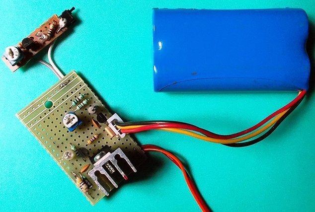
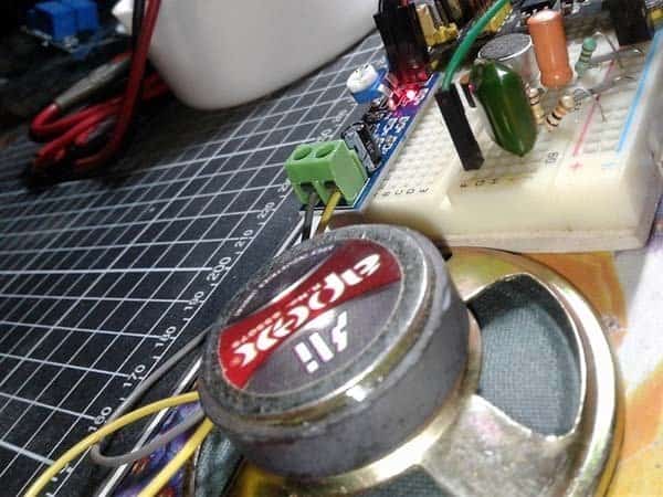
To test and demonstrate the design I built a breadboard prototype as shown below.
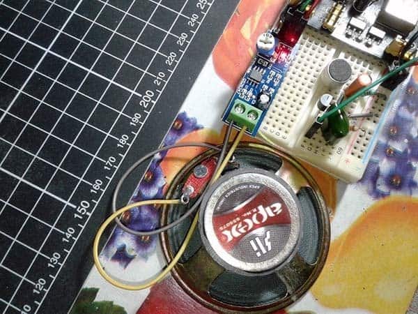
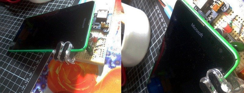
For testing my primitive model, a mobile phone was reposed very close (~ 50mm) to the microphone with the aid of a slanted mobile phone tail clip (see next snap). This proved ideal for initial testing purposes but when the unit is fitted into the enclosure it may, for example be more comfortable to place the mobile phone on the topside of the enclosure.
Note that, in order to save much time and money, a prewired LM386 module was used for the quick test. The LM386 low voltage audio power amplifier module is ideal if you need a small amplifier for your audio experiments and prototypes. However I used a customized version as I substituted certain components in the original board with those of my choice to run the model successfully as intended. You can refer this article to play along with the cheap eBay LM386 module https://www.codrey.com/electronic-circuits/little-audio-amplifier-lm386/
Component List
In order to clearly identify the components, I’ve listed them in the following table.
| R1 | 2K2 ¼ w |
| R2 | 100K ¼ w |
| R3 | 10K ¼ w |
| R4 | 2K2 ¼ w |
| R5 | 10Ω ¼ w |
| P1 | 10K volume control with switch |
| C1 | 10uF/16v |
| C2 | 100nF |
| C3 | 100nF |
| C4 | 100nF |
| C5 | 100uF/25v |
| C6 | 100nF |
| C7 | 10uF/16v |
| C8 | 1uF/16v |
| LED1 | Red 3mm |
| D1 | 1N4007 |
| T1 | BC547B |
| IC1 | LM386 |
| ECM | 4-8mm electret condenser mic |
| SP1 | 8Ω /1W loudspeaker |
Epilogue
Simplest adaption of the acoustic coupling method is sensitive to external noise and depends on the type, dimension, and performance of the mobile phone handset/portable music player. Nevertheless, the acoustic coupler idea greatly simplifies the electronic interface to a considerable extent. Probably I’ll come back with the circuit of an inductive audio coupler within a couple of weeks. Meanwhile give this project a good try because with luck you could get superb results. As always, in the beginning you must be able to walk firmly on the ground before you start walking on a tightrope!