Monitoring entry/exit doors on time is not always an easy task for everyone. Fortunately, with a handful of electronic parts you can build yourself an expansible door sensor that will not only give a timely indication, but also offer an isolated electric switch to control an external electric load such as a hooter and or a strobe light. I deliberately kept the circuit as simple as possible (no costly modules or hard to get discrete components) so it’s possible that you can build it within a couple of minutes!
Circuit Talk
I know that even an average electronics hobbyist can build a cheap ‘n’ cheerful door sensor with the help of one permanent magnet and a reed switch. The design presented here is again a magnetic door sensor but with a low-profile (and less fragile) Hall-Effect Switch employed instead of the relatively bulky (and fragile) ordinary reed switch. Okay, let me show you the tried and tested circuit diagram of my expansible door sensor.
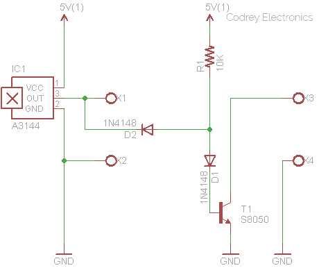
Key component in the above circuit diagram is the A3144 (IC1) Hall-Effect Switch from Allegro® MicroSystems Inc. (www.allegromicro.com)
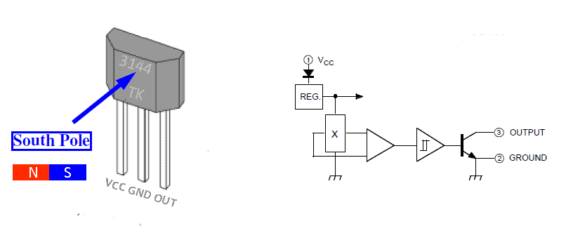
The A3144 includes a voltage regulator, reverse battery protection diode, Hall voltage generator, small-signal amplifier, chopper stabilization, Schmitt trigger, and an open-collector output on a single silicon chip. In the presence of a south polarity magnetic field of sufficient strength, its output switch turns on and stays in that state until the absence of the south polarity magnetic field, or when a north polarity field of sufficient strength is present. The open-collector output can sink current up to 25mA, and A3144 can be operated with DC supply voltages of 4.5 to 24 volts. Note that, the open-collector output naturally needs an external pull-up resistor (~10K) when used with bipolar or CMOS logic circuits.
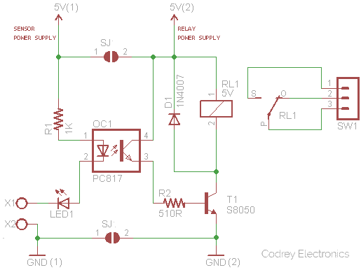
Here, first output channel (X1-X2) of the circuit can control one electromagnetic relay through a suitable driver circuitry. Likewise, the second channel (X3-X4) can drive another electromagnetic relay through a driver circuitry which is an exact replica of the first one. The design is deliberately configured in such a way that when first channel turns on, the second channel will turn off, and vice versa. Circuit diagram of the electromagnetic relay driver circuitry is shown below. Remember to replicate the circuit exactly for making the second channel electromagnetic relay driver.
| IC1 OUTPUT | X1 | RL1 | X3 | RL2 |
|---|---|---|---|---|
| HIGH (idle) | HIGH | OFF | LOW | ON |
| LOW (active) | LOW | ON | HIGH | OFF |
Using the second part of the circuit (relay section) in combination with the first one lets you switch two independent electrical loads (10A @ 250VAC maximum) one at a time at ease. Naturally one of the relay has to be powered for as long as its connected output load is required, and a typical 5V electromagnetic relay might draw around 75mA or so (assuming a 5V coil with 67Ω resistance) but in real terms it’s nothing to worry much about if the circuit is powered by a suitable mains adapter. For battery operation it’s another matter though, as every milliamp counts!
Installation Hints
The device installation on the door takes only a few minutes. First of all, attach a bar magnet (or a suitable Neodymium magnet) on inner top edge of the door. Next, mount the Hall-Effect switch on the door frame in a position such that when the door closes, it’ll be triggered by the South pole of the door magnet. Make sure that, branding side of the Hall-Effect switch is facing the South pole of the magnet, and gap between them is within 5mm.
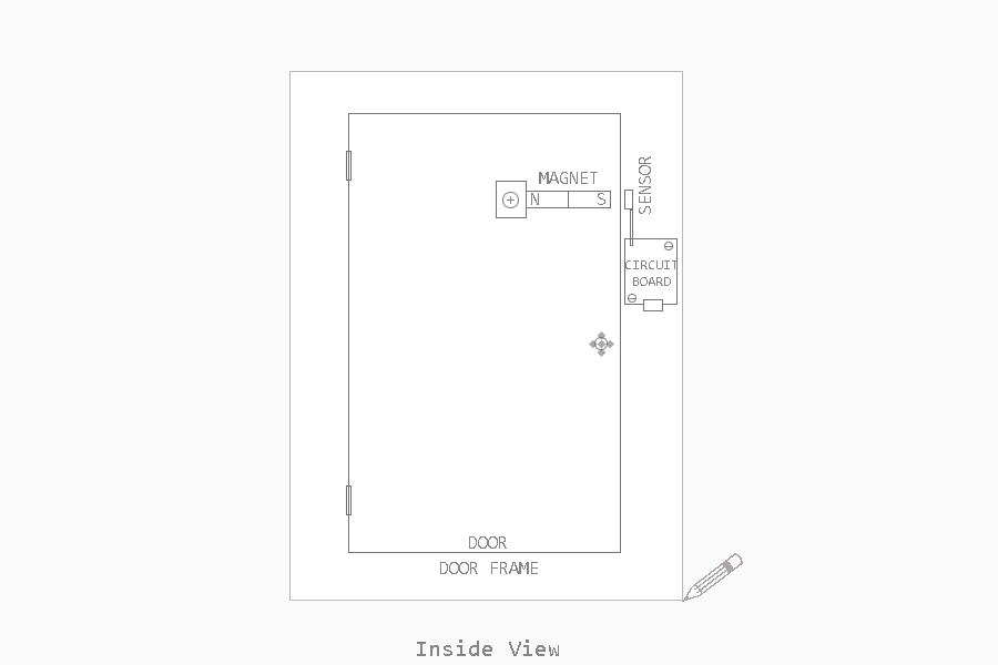
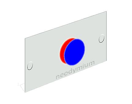
Broad range of powerful Neodymium magnets in various shapes and sizes are now available at ground bottom prices. So it’d be better to opt for an N52 (highest grade) Neodymium magnet rather than trying an ordinary bar magnet to make your door magnet plate.
Lab note
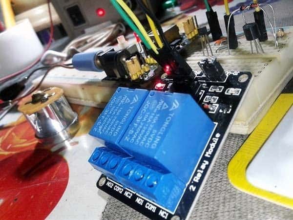
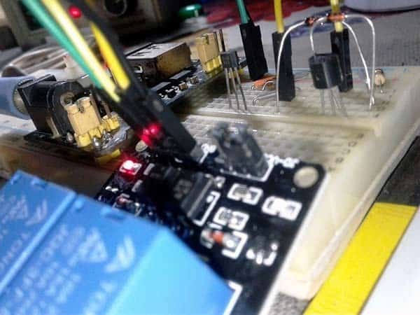
In the accompanying photographs you can see a powered-breadboard with the 3144 Hall-Effect sensor circuit, and a readymade 5V relay module with two electromagnetic relays (near-similar to the one shown below).
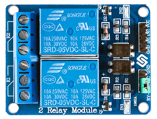
The module is a 2-channel relay board I used to complete my experiment setup that helped to make the initial test much easier than repeatedly soldering and de-soldering various parts. You sometimes see them on websites or in the shelves of shops selling electronics parts. But don’t worry about that because the circuit of that prewired module closely resembles my own relay driver circuit posted here. Much pleasant soldering!