Nothing mattering to see a circuit turning light emitting diodes (LEDs) on and off. If for certain applications, brightness of the LEDs could be adjusted in a continuous manner, with a simple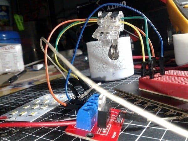 dimmer circuit you can have a moderately smooth continuous control of the light output. All the circuits are freely available everywhere on the web. Admitted! But what’s your feeling about getting an inexpensive and easy to build LED strobe light circuit? Again, such LED strobe lights (LED stroboscopes) are available ready-made, still if you make one yourself the key benefit is that that you can tinker it just the way you desire. And for this reason, simplest circuit of a do-it-yourself little LED strobe light is presented here for avid electronics hobbyists and makers.
What is a strobe light?
Strobe light is merely a pulsing light. Just to exemplify, the common photoflash unit can be referred as a single-pulse type strobe light, while series-pulse type strobe lights can be seen mostly in discotheques. Strobe light with an adjustable pulse frequency is great for observing repetitive events to halt them, slow them down, or reverse them, by adjusting the frequency of the strobe.
Moreover, strobe light is an essential part in today’s high-end flashlights (torches) as such a flashlight is not just a tool for illumination but a small self-defense weapon that saves the user’s life in the right situation. It’s a proven fact that strobes can be used against offenders and opponents as the rapid succession of light/dark phases makes it hard to focus/recognize the defense/attack motility.
In short, strobe light, stroboscopic light, or the strobe is actually a special lighting device that is being utilized to yield brief light flashes. Strobe lights are widely used in industrial and medical fields too. Since strobe lights can grab public attention more effectively, they’re used as beacons in emergency vehicles, as well.
Your own strobe light
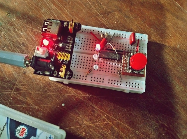
The LED strobe light introduced here is just an entry-level electronics hobby project. If you’re just learning about (or interested in) strobe lights and you won’t be working on a do-it-yourself strobe light project, I would strongly recommend starting with this minuscule one. Anyhow, the design is centered on a Digispark Attiny85 development board, and for the reason newcomers are requested to read Digispark-related articles and Digispark-powered experiments/projects published here to catch the ball very easily!
Now let me share the hardware setup diagrams:
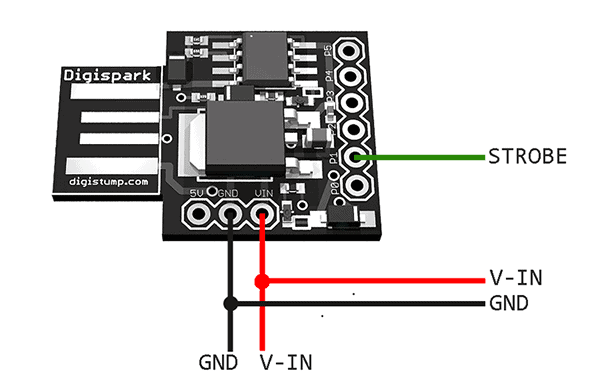
Proposed wiring diagram of the Digispark hardware is pretty simple because only one I/O pin (P1) is utilized here to deliver the strobe pulse. Remaining two connection points (V-IN and GND) are for inputting an unregulated DC supply to power up the Digispark board. The VIN pin of Digispark takes 7V-12V (6V-32V may work but over 12V will probably call for some heat sinking). Also note that the 5V regulated output of Digispark (not used in this project) can cater 500mA of current, but over 100mA might need proper heatsinking.
Strobe pulse output (P1) of Digispark controls the strobe through an LED driver wired around one cheap power mosfet (IRF520N). The LED panel comprises twelve white SMD LEDs (WLED1-12), actually a parallel combination of six WLED strings (one strings holds two series-connected lamps). See its circuit diagram below. The entire hardware setup is prepared to run on any 12V DC unregulated/regulated power supply capable of delivering minimum 1A current at 12V.
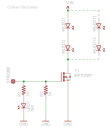
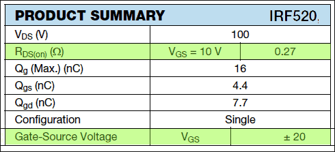
The IRF520N power mosfet in TO-220AB package is universally preferred for all commercial-industrial applications at power dissipation levels to approximately 50W. See the product summary published by Vishay Siliconix (www.vishay.com) below. Frankly, it’s not a perfect pick for this project because of its ± 20V VGS rating (VGS(th) = 2-4V). Since the power mosfet is driven by the I/O of a 5V microcontroller, a logic-level power mosfet, like the IRL540, will obviously render better results (Gate-Source Voltage (VGS) of IRL540 is ± 10V & VGS(th) = 1-2V). So, make it a try!
Following is the ready-to-use code/sketch for Digispark LED strobe light.
/* Digispark LED Strobe Light  ::  Inspired Project  ::  Thanks to Vortecks */

const byte strobePin = 1; // P1 as the strobe pulse output pin

void setup() {
  pinMode(strobePin, OUTPUT); // Set P1 as output pin
  digitalWrite(strobePin, LOW); // Set P1 output to LOW (0V)
  delay(2000); // Wait Time
}

void loop()
{
  for (int i = 0; i < 2; i++) // Strobe Pulse Pattern
  {
      digitalWrite(strobePin, HIGH);
      delay(10);
      digitalWrite(strobePin, LOW);
      delay(100);
  }

  delay(2500); // Wait Time


} // End of Code
Is it DANGEROUS?
The British Health and Safety Executive advocates that a strobe light’s flash rate never exceed five flashes per second. Why? Because strobe lights can cause epileptic seizures when used on photosensitive people! Let me explain what happens when you get “strobed”.
A typical commercial strobe light has a flash energy in the region of 10-150 joules and has a discharge time shorter than a few milliseconds. Since this results in a potent flash of several kilowatts power, the corneal flash burns are a painful ocular condition. There are a lot of debates about the side effects of strobe lights and it’s claimed by many that strobe lights make someone vomit and seizure. Furthermore, it’s pointed by experts that most strobe lights also trigger photo-sensitive epilepsy if used improperly. Even though a modest type, the LED strobe light project shared here is not suggested for continuous lighting as it induces some people acute vexations. Beware!
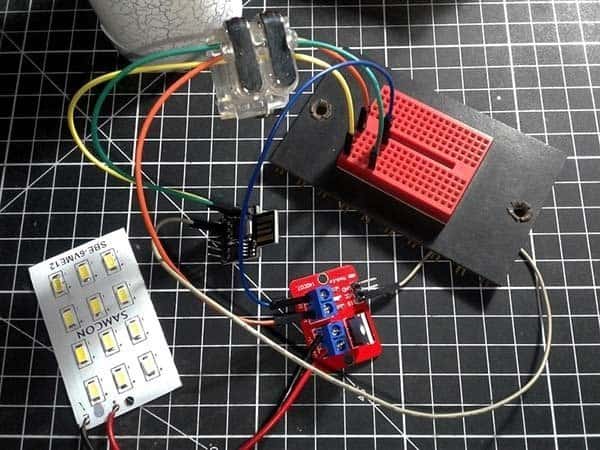
Next is two random snaps of my quick test setup. As you might noticed, I made up the quick test setup with one readymade WLED panel and one IRF520N mosfet module. It’s done deliberately because even though I’ve all discrete parts in stock, just for quick testing I decided not to trouble them!
Furthermore, two quick test movies are included here for the curious readers. Sorry for the wretched videos – it’s my mistake. Shooting a strobe light experiment (at times) with a smart phone camera is challenging even though it’s a high-end camera phone. Strobe lights wreak havoc on the shoot process, hence the exposure simply didn’t catch a good strobe. Since we’re not triggering/synchronizing the strobe effect ourselves, the sync control will become another task little harder to wield. Further serious explanation may be difficult to empathize, so I come to a halt (may be riposted later). That’s all! Good luck with this project. Happy Strobes!
References
It’s not the ” ± 20V VGS rating” that makes the IRF520N a poor MOSFET choice — in fact, that’s an excellent spec. It means up to 20V, plus or minus, can be applied to the gate, and the MOSFET won’t be harmed — that’s quite resilient! Here are two things, on the datasheet, that flag this MOSFET as NOT “Logic Level”:
1. The fact that, on the datasheet, only one RDS(on) value (“0.20Ω”) is specified, and that’s at VGS = 10V. So, the datasheet sheet doesn’t even consider Gate voltages below 10V [other than on some of the graphs, but even there, 5V on the Gate shows pretty dismal performance].
2. The VGS(th) Gate Threshold Voltage specification, which, for the IRF520N is: 2.0-4.0V. If you consider that this is the Gate voltage where the MOSFET STARTs to conduct, you might see the problem. If you get lucky, the IRF520N in your possession, happens to have a VGS(th) of 2V, then you might be OK. But, if your luck is not so good, and you have one of the 4V threshold devices, by the time the Gate gets to 5V, the transistor is still not going to be allowing anything near the 9.7A rating.
The article doesn’t seem to state how much current those “WLED strings” run at [also, there damn well better be a current limiting resistor in series with each string], but the 12V Power Supply is apparently rated to 1A [the article uses the term “minimum”, but I suspect the author meant “maximum” — and judging by the VGS faux pas, this is consistent with a clear misunderstanding of “Max” specifications].
A look at the Typical Output Characteristics graphs, gives a warm-fuzzy that this MOSFET ‘might’ work just fine, even in the worse-case VGS(th) = 4V case — but, an engineer, in a production environment, would NEVER do this. In in a one-off, hobbyist environment, what the heck.
Other than that, fun project, and thanks for posting!
* 12V/1A minimum power supply:
This adaptable design is based on Digispark Attiny85 development board. According to Digistump, the VIN pin takes 7-12V (6-32 may work but over 12 will probably need some heat sinking) and can output 500mA (but over 100-200 might need some heat sinking). And particularly for expansible projects, a 9-12V/500mA (minimum) power supply is recommended by Digistump for their 16.5MHz boards (integrated with 78M05 linear voltage regulator).
** Series Resistor/LED Current Limiter:
The white LED panel alone draws about 350mA of current at 12VDC. Since it’s a readymade Chinese board with chip LEDs, it might not possible to insert current limiting resistors in between strings. You can certainly add an appropriate single resistor in series with its power supply line, but I still prefer my ‘tricky’ method as the model is just a strobe light, not a search light.
*** Poor Mosfet Choice:
Oh sorry…You (perhaps some other readers) took me in the wrong sense. What I meant is that we’re over killing such a +/- 20V mosfet, while a logic-level one can play the role pretty well. The decribed design apparently calls for a logic-level mosfet, and it’s clearly mentioned in the article, At first I tested it with IRLZ44 and later moved to the pre-wired IRF520 mosfet module for certain reasons.It works, but the efficiency will be rather poor (we don’t have a current-hungry output load here, anyway).
Looking back at it – “Frankly, it’s not a perfect pick for this project because of its ± 20V VGS rating (VGS(th) = 2-4V). Since the power mosfet is driven by the I/O of a 5V microcontroller, a logic-level power mosfet, like the IRL540, will obviously render better results (Gate-Source Voltage (VGS) of IRL540 is ± 10V & VGS(th) = 1-2V)”. See, I already pointed out the VGS(th) ratings there, and I’m well aware of the conflict amongst standarad and logic level mosfets.
& Finally:
As always,design ideas shared here’re “rough drafts”, but by working together we can make them pretty definitive. And I believe, our clever readers not ever try sending a “proof-of-concept” out for high-volume production. Trust me, theory is nice but in real-world practice not everything is exact, even if exact, the end results sometimes won’t be cheering!
I’m glad, you make some very valid points – worth looking into.Thanks for the thorough read through!
I’m looking for a strobe that can stop motion in a frequency range between 5 and 200 Hz. Can your design do that?
@Frank Rauch: My understanding is that if the strobe light’s frequency is right, a rotating object will be illuminated at the same position during each strobe, thus giving the appearance that is stationary (the stroboscopic effect).
I have thought of using an improved code (and a bit of extra hardware) to build an expansible strobe light with 1 Hz – 500 Hz user-adjustable frequency range. Hopefully you’ll see the revised project in the near future.
Meanwhile, if you’re an experienced electronics hobbyist/maker, refer this project to catch an idea https://softsolder.com/2013/01/03/arduino-snippets-led-stroboscopic-tachometer/. Thanks, Have Fun!