Let’s make a quick and dirty foam cutter! Foam is an easy and cheap material for various prototype creations, and cutting the common polystyrene/Styrofoam is easy with a hot wire cutter. Now 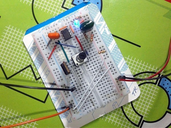 do it yourself ideas on hot wire foam cutters are everywhere on YouTube and there’s dozens of sites with their own exclusive versions. However I’ve got a couple of ideas and wanted to make one for a long time now and finally I found a cheep and cheerful solution. Although I’ve decided to share my rude idea here, I don’t want to cover the build in too much detail, but It sure this post will enable even a complete novice to make one from scratch. So let’s build it!
Let’s get started
At first you need to note that polystyrene vaporizes at certain temperature. A foam cutter is merely a hot wire that pass through foam like a hot knife through butter. The Simplest way to make the hot wire is connect certain length of Nichrome wire to an appropriate high-voltage AC (but very dangerous) or low-voltage DC (much better and safe) power source.
As with most of my basic/simple projects, I work with whatever stuff I have to hand and you ofcourse can follow the same practice to save some bucks. The project idea presented here is extremely easy to develop and all of the requisite parts you can get from a local electronic store.
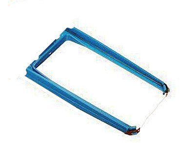
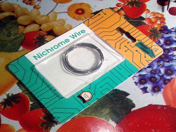
The first step in building the foam cutter is to take a piece of Nichrome wire. I got mine – a big packet – from Flipkart for cheap. Next, mount the Nichrome wire on a convenient frame – I made it like a kind of fork (inspired by the image shown below), with the Nichrome wire tied to its lugs, and the power supply wires were fastened directly onto the ends of the ‘hotwire’. You can also construct it similar to a small bow. Then do connect the power supply wires to the hot wire using cable lugs and secure them to the frame with nylon cable ties to make the build more elegant.
On a side note, I’ve seen some other makers trying different hotwires they made from certain guitar strings, René wires (mix of chromium and molybdenum), and so forth instead of the standard Nichrome wires. I guess, those alternatives might have better stiffness and electrical resistance, making them more befitted.
Heat control is the secret for making good foam cuts. So you now need a ‘regulator knob’ to adjust the hotwire temperature i.e. to control the current going through your hot wire. You can’t use a big potentiometer/rheostat because it’s too impractical for a Nichrome wire heater. Instead, you can use a pulse width modulation (PWM) controller circuit because such a great circuit can turn on the hot wire power for a brief while, then turn it off and does this iterate many times per second. The following circuit is a simplified intermix of several older designs. The easy to build circuitry uses readily available components, and has reasonable temperature control for both a short and long hot wire.
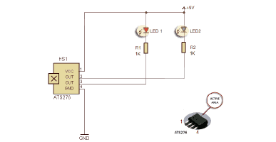
The adaptable design, centered on the ubiquitous tiny timer chip NE555, is tailored to run preferably on a 12V(5A minimum) industrial grade SMPS. The design is a ‘minimalistic’ astable, as apart from the basic support components that are always called for, it needs just one resistor and one capacitor. Frequency is calculated from the formula f = 0.7/ ( R1 × C1 ).
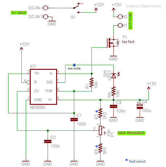
With the components values shown, the basic astable frequency will be around 700Hz. You can see that the ‘discharge pin’ (Pin 7) is used to drive a green indicator (LED1), but you can take a ‘spare’ astable output from it too. The LED is entirely optional, but it helps you to see what the 555 chip is doing!
Further, the ‘control voltage pin’ (Pin 5) is used in this circuit to control the trigger and threshold levels. As you may know, the timing of the 555 IC can be modified by applying a voltage to this pin, either from an active circuit or by wiring it to the wiper of a potentiometer connected between power supply rails. The latter technique is employed here to simply regulate the hot wire temperature within a limited scale. Needless to say, the 10K potentiometer (P1) is your ‘regulator knob’.
A power mosfet STP60NF06 (T1) was used to test-drive the heater coil i.e. the hot wire as it’s only available at that time. You may wonder why the usual ‘gate’ resistors are not included in the schematic. It’s not very crucial but you can insert those parts if your prototype necessitate them. Anyway, don’t forget to pick an appropriate heatsink for the power mosfet, and sufficiently thick wires for interconnection between the hot wire and power mosfet!
Back to the PWM idea, the way the given circuit works is not different from the basic astable, except that the duty cycle (also a bit of frequency) is variable to a certain extent by means of the aforesaid potentiometer. As you can see in the following Pin 3 oscillograms (minimum and maximum regulation) feeding a variable voltage to pin 5 will change the duty cycle (and period) by changing only the amount of output high time while keeping the amount of output low time constant. In principle, the variation is linear if Vctrl < 2/3 Vcc, so take that under consideration if you tweak your prototype.
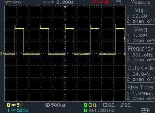
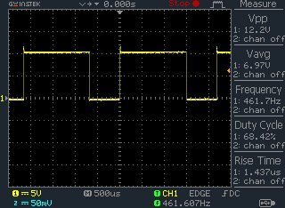
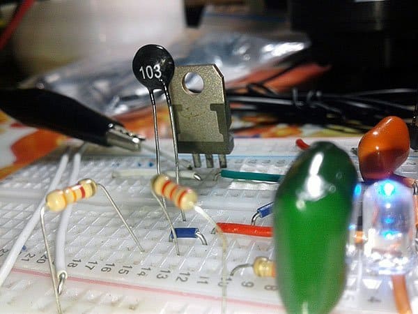
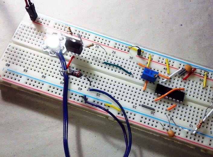
One minor drawback of this idea is that you can’t regulate the full 100% of the pulse width. The minimum is okay at about 30%, it let’s the hotwire heats up slowly, but the maximum is only about 70%. Frankly, I was not 100% sure that my heat controller design idea would be good for my intended use, that’s why I decided to throw together a very quick build to test it out. At least it’s okay for my proposed application as it works really well especially with less dense polystyrene foams. This is my rapid assembly of the PWM heat controller circuitry wired on a mini breadboard.
Unless you are an experienced in electronics maker and can follow a detailed circuit analysis, the control voltage pin trick probably won’t mean a great deal to you. It should be made clear that the astable operation can be tuned by changing R1-C1 values, but the odd trickery will enable you to control it through a passive or active external circuitry as mentioned earlier. For example, you can add a 10K NTC thermistor in place of the 10K potentiometer to build an automatic temperature controlled hot wire. If you really do need a bit of precision, use an op-amp based thermistor circuit – with a TL081 op-amp for instance – to do that, it too has many foibles, though. To be useful, keep note that the control voltage input of 555 is often overlooked, but it can be used any time you need to create a voltage controlled oscillator (VCO). In another article, I’ll talk about an advanced foam cutter I built recently that smoothly cuts any foam into slices!
Addendum
The bit of 24SWG Nichrome wire I used in my initial design has a very low electrical resistance of 3Ω approx, thus took a whopping current to got hot enough.
Finally, this isn’t an exact method as you can construct the project very much to your own actual requirements, but the idea presented here is a good steer. So spend some time tinkering until your version is aright. And that’s it! Turn on and voila! Quick & Dirty Foam Cutter!

Hi and Thank you. I made it and it works 🙂
My first idea was to create regulator with only potentiometer, capacitor and darlington transistor. It works with dc motor but not with the wire. Then I try to make regulator like servo tester with 555, there are many similar circuit on internet, tested one with a 2N2222…and same issue, overheating transistor and works only with dc motor. Finally I find your circuit and it works. I using the same components except potentiometer (I dont know value, maybe 1K) and without R3 R2. My wire is cca 20cm long 3,45 Ohm/m 0,4mm..in full power starts shining:)
Also I find out that it works perfect only with 12V, pretty cold MOSFET even without heatsink, but with 9V battery MOSFET starts overheating.
Martin: You’re welcome! I’m glad you found this useful, and noticed that you have successfully built one. Congratulations!
Just a note on MOSFET heating issue with 9V:
With 9V DC, the gate voltage is probably not sufficient for a good switch-on operation of the MOSFET. In order to achieve a low switch-on resistance (RDSon), a considerably higher gate voltage must be applied ( e.g. 10 V).
Further, in order to control the MOSFET with high impedance, i.e. to switch it off, the gate voltage must be permanently and significantly below the threshold voltage.
Generally speaking, a MOSFET is designed to dissipate minimal power when turned on. And the MOSFET must be turned on hard to minimize dissipation during conduction, otherwise it will have a high resistance during conduction and will dissipate considerable power as heat!
Good Luck!