 Perhaps you will try tomorrow one microcontroller experiment that can store variable data in its EEPROM (electrically erasable programmable read only memory). Presented here is an idea to use inbuilt EEPROM of Arduino to save data between power cycles. EEPROM is a type of non-volatile/flash memory simply stores data even with its power removed. Fortunately, all Arduino models have inbuilt EEPROM available, and it is incredibly useful because it remembers data even when the power is unavailable, you could store the state of the Arduino. This guide is a minimalistic approach to detect sudden power down and automatically store a variable to an EEPROM address.
Add-On Hardware
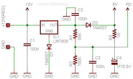
First of all, see the simple add-on hardware setup for Arduino Uno. Note that this approach of course works for other models of Arduino as well. The hardware is in fact nothing but a regulated linear power supply backed by a super capacitor, with a crude power-down detector circuit. The linear power supply is used to deliver regulated 5V dc to the Arduino board while the power-down detector is wired to give a steady high-level input to one interrupt pin of Arduino as long as the input power is available. During a power-down condition an Interrupt Service Routine (ISR) is triggered that stores the variable to a pre-defined address of the EEPROM. The super capacitor ensures that the Arduino has enough power available to safely detect the power-down state and store the requisite ‘volatile’ variable to the EEPROM.
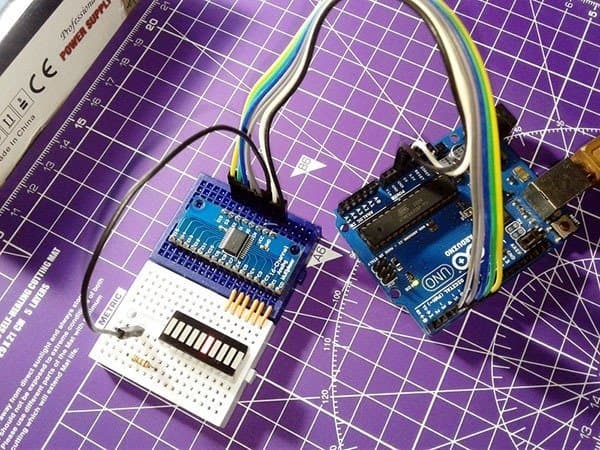
First Hardware Test
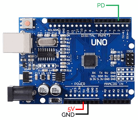
For testing your add-on hardware, simply complete the setup as pointed below. Next, upload the test code to Arduino, and power up the entire setup. Since the input power is available, connected INT pin of Arduino Uno ‘sees’ a high-level voltage (greater than 3V) and nothing takes place until you switch off input power to the hardware. If switched off, you can see that the onboard LED (D13) of Arduino starts flashing to indicate a power-down condition.
// Power-Down Add-On Hardware Test Code
const byte ledPin = 13; // Onboard LED
const byte interruptPin = 2; //D2
volatile byte state = LOW;
void setup() {
pinMode(ledPin, OUTPUT); //D13 as Output
attachInterrupt(digitalPinToInterrupt(interruptPin), blink, FALLING); // ISR
}
void loop() {
digitalWrite(ledPin, state); // Enable LED
}
void blink() {
state = !state;
}
Backup Time Calculation
It’s assumed that Arduino will work until 5V from the 1F/5.5V super capacitor drops to about 4V, and the maximum current demand is well below 100mA. My Arduino Uno (16MHz/5V) used for the test setup itself took about 48mA of current. If so the ‘theoretical’ expected backup time extends up to 10 seconds (t= ∆VC/I = (5V-4V) x1F / 100mA = 10s) – enough well to store a variable. Remember, peripherals (if used) are in switched off state at power-down as they are wired here on a separate 12V power rail.
EEPROM Read & Write
Now let’s look at how to write and read some data in real-world. Here is a half-baked example code:
// Save variables automatically to Arduino EEPROM on power-down

#include <EEPROM.h> // Library comes with Arduino IDE

int SomeVariable; // Some Variable
int PD_PIN =2; // D2 used for  power-down detection (INT.0)

int EE_ADDR = 0; // The EEPROM address to be used

void setup() {

  EEPROM.get(EE_ADDR, SomeVariable);   // Retrieve last stored value of SomeVariable from EEPROM

  attachInterrupt(digitalPinToInterrupt(PD_PIN), PD_ISR,FALLING); // Set-up Interrupt Service Routine (ISR)
}

void loop() {
  // Do something great
  }

void PD_ISR () { // ISR to be get called on power-down state

    EEPROM.put(EE_ADDR, SomeVariable); // Put SomeVariable to the EEPROM

}
For more details, do refer EEPROM examples in the Arduino IDE as it’s good and worthful indeed (practice makes perfect)!
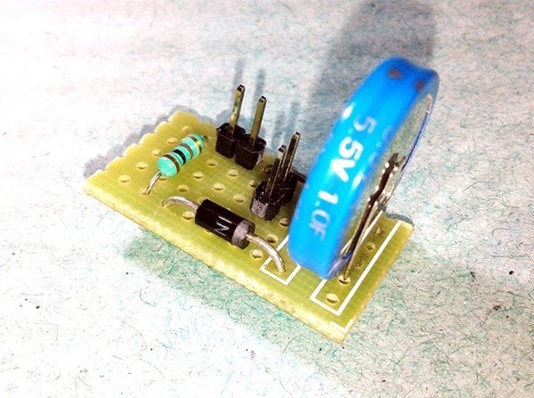
& finally, the “super capacitor module” prepared by me for the experiments:
Wrapping Up
With Arduino, the built-in EEPROM is a pretty cool way to store data permanently. The Arduino boards (Atmega328P) have an emulated EEPROM space of 1024 bytes. Each EEPROM position can save one byte, i.e. you can only store an 8-bit number (you cannot write letters) which includes integer values between 0 and 255. Keep note that you don’t write too often to the EEPROM as it has a limited lifetime (erasing memory also is a writing operation). Interesting to note is that Arduino’s EEPROM is specified to handle 100,000 write/erase cycles for each position i.e. each memory cell of the EEPROM can be accessed a hundred thousand times before burnout.
Functions:
- EEPROM Clear = Clear the bytes in the EEPROM.
- EEPROM Read = Read the EEPROM and send its values to the computer.
- EEPROM Write = Store values from an analog input to the EEPROM.
- EEPROM Get = Get values from EEPROM and prints as float on serial.
- EEPROM Put = Put values in EEPROM using variable semantics.
- EEPROM Update = Store values read from A0 into EEPROM, writing the value only if different, to increase EEPROM life.
The EEPROM documentation on the Arduino website has lots more examples (https://www.arduino.cc/en/Reference/EEPROM)
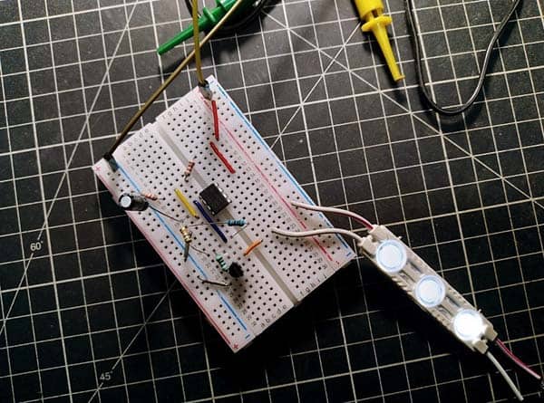
Thanks for sharing this. Exactly what I was looking for. I’ve built it on breadboard and it works great. I think I’ll get a PCB made up for my project.
@Luke Hurst: Thank you for your valuable feedback. Appreciate it and I’m glad to hear that it’s of value for you!
PCB for this small project is not designed yet as I tested it on a bit of perforated circuit board. If you’ve designed a special PCB for you, I’ll be happy to know more on that. Cheers!
Hi. I’ve designed the PCB and had some made. It works great. Drop me an email and I will share details with you.
Luke Hurst:
That’s nice! I’m especially interested to see how it came out. Could you take pictures of your PCB and send them my way (designlab.technode@gmail.com). I’d be happy to link to it on this page. Thanks!
Hi Luke & T.K.
Good job, thanks.
Would like to build one too. Can I buy the PCB from you Luke.
Henk Wijtman
Rotterdam
the Netherlands
Luke Hurst: Thanks for sharing a couple of Images of your PCB design with me. Great work. Delighted!
Henk: My pleasure! I know that you need to hear from Luke.
Luke: I’m waiting for you to respond. Thanks!
T.K.
Maybe you can write Luke an email to ask if he could contact me (you have my email and you can give it to him). Or ask him to look at this website/comments again. You do not have to post this post in your comments.
Thanks
Henk
Hi
Sorry for delay replying. Had a busy couple of days.
If you contact me via my website retromini.co.uk I will sort something out for you.
Regards
Luke
Looks good. Thank you Mr Luke!
Dear Henk
Perfect! I’ll share your email address with him. Thanks…
T.K.
One other question. For debug purposes (reading print commands in the serial monitor) it would be nice to connect the USB connector as well. As far as my knowledge goes this could cause a problem when 2 power sources are used.
I use an Arduino Ethernet board where the USB connector is located on a small extra FDTI-USB to Serial board. Can I use both power sources at the same time without damaging the Arduino ?
Henk
Henk : I regret, sadly I’ve very limited experience with Arduino Ethernet shield. Anyway I’ll take a deep look, and share my thoughts here. Thanks!
T.K.
It’s not a shield. The Ethernet is embedded in the Arduino (Atmel MEGA328P)
https://store.arduino.cc/arduino-ethernet-rev3-without-poe
https://www.sparkfun.com/products/retired/11229
to program it witch USB you need:
https://www.seeedstudio.com/Arduino-Ethernet-WITHOUT-PoE-USB2SERIAL-p-1068.html
Henk
Henk: Okay, well, thank you for clarifying that. I already tried some internet over serial experiments with Arduino, and have (a bit old) Arduino Ethernet with PoE that has a Wiznet Ethernet interface, handy but not tried yet.
Coming to your query, now I’m working on the next edition of this project (UPS for Micro-controllers). You can of course see it here in next year. I’ll try to include a few additional.demanded features in it. Please stay tuned…
I connected output from my 5vdc power supply per schematics, did not install D1 diode though, everything else the same per your drawing on the output.
I see voltage drop to 4.2vdc at pin 5v.
Also I have about 300-350mA draw from the power supply, as I have display connected.
Any idea?
Thanks
Rock
@Rock: If you want to use an external dc power supply, just omit 7805 (and the surrounding parts) and feed around 5.7VDC input (not 5V) across C2. If so, you’ll get circa 5VDC at the output.
I’m afraid, the back up supply from the supercapacitor C4 is not amble enough to support the LCD in power down mode. Thanks!
That is what I thought.
Even 4.2v for VCC will do the job, just reference that voltage to analog readings and I should be fine, correct? without having to re design the supply voltage.
Regarding the super capacitor, what do you think correct capacitance should be?
I did try 3f and it does not seem enough, any idea? there is around 400mA current draw to be precise.
Many thanks for the reply.
Rock