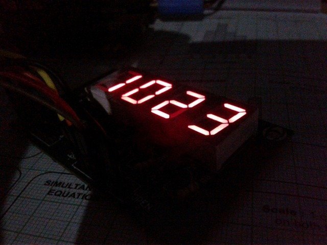
 Hello everyone, today we’ll learn how to rig up a simple system to read and display the value of an analog sensor using Arduino and a seven-segment LED display (SSD) panel. The presented setup will read the ‘value’ of the connected analog sensor and displays the values as numbers ranging from 0 to 1023 (2^10=1024 so range will be from 0 to 1023). The idea is very helpful because quite often you wanted to know the value of a selected analog sensor (under different conditions) so that you can include it in your code prepared for a specific microcontroller. Just to exemplify, light dependent resistor (LDR) is a key component in automatic light switch projects which usually has 1MΩ (min) light resistance at o lux and around 6-20KΩ at 1o lux.
You can ofcourse wire the LDR as the part of a potential divider to feed the light-to-resistance values to one analog input of a microcontroller. However, for threshold settings you should include suitable values (0-1023) in the code. The given idea is so helpful as you can find out the requisite values before starting your actual experiment, that allows you prepare the code in advance to expedite the overall modeling process.
7-Segement LED Display Board
Let’s start with the construction of the display panel that’s nothing but a bunch of four 7-segment (common cathode) multiplexed LED displays. Shown below is the schematic of the display board.
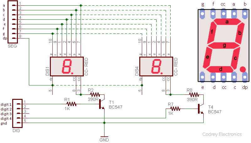
Actually, SSDs are mere arrays of seven LED segments with additional decimal point (dp) which is also an LED. Each these segments are marked as a,b,c,d,e,f,g (and dp). Multiplexing is essential to drive two or more seven segment displays by a microcontroller. Here, due to the multiplexing trick, only 7 segment-lines and 4 digit-lines are required for the four-digit LED display i.e. total of 11 connections (or 12 if the decimal-point segment is used, too).
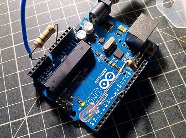
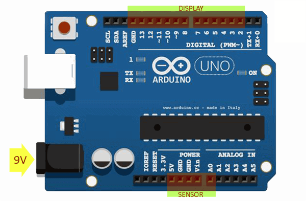
Arduino Hardware Setup
In the above circuit we used common-cathode type SSDs with anodes (segments a – g /dp) of each LED display are all connected together and then connected to an I/O line of Arduino. Each common cathode is connected to transistor and it is controllable by an I/O line, as well. I/Os D2 to D5 of Arduino is connected to ‘digits’, and ‘segments’ are connected to I/Os D6 to D13. There’s also a single ‘ground’ (gnd) connection.
| Display Pin | Arduino I/O |
|---|---|
| Digit 1 | D5 |
| Digit 2 | D4 |
| Digit 3 | D3 |
| Digit 4 | D2 |
| Segment a | D6 |
| Segment b | D7 |
| Segment c | D8 |
| Segment d | D9 |
| Segment e | D10 |
| Segment f | D11 |
| Segment g | D12 |
| Decimal Point (dp) | D13 |
| Ground (gnd) | GND |
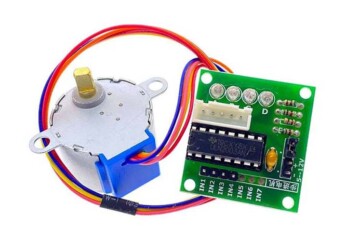
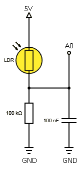
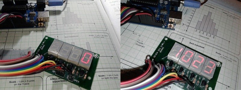
Next is the simple hardware setup diagram for LDR test. After completion of the setup you can expose the LDR to different light levels to get readings on the LED display. You can obviously replace the LDR with another analog sensor like a thermistor (PTC/NTC type) or a force sensing resistor (FSR) or a turbidity sensor. You may go then with another value resistor instead of the used 100K one, too. Be careful, never apply a dc voltage more than 5V to the sensor interface as it’ll kill the concerned analog I/O port of Arduino (or the entire Arduino microcontroller) in a flash. Remember, basically there is a variation on the ADC readings of Arduino with lengthy wires, so always try to put the potential divider (sensor + resistor) very close to the analog I/O header of Arduino (to get more stable values with less noise).
Experimental Code
Following is the example code for the project based on Arduino Uno microcontroller board. In order to display numbers, byte representing number must be sent to the segments, and transistors must be activated by enabling corresponding I/O pin by applying high-level at the base of the ‘digit’ transistor. At any particular time, only one of the segments is turned on. Immediately after illumed, the segment is turned off and the next segment in the execution is turned on. Thus each digit is switched by controlling the cathode for that display. If you do each one fast enough, you can see a flicker-free display.
/*
* Arduino Analog Sensor Reader
* Hardware: Arduino Uno with 4x Red SSD (common cathode)
* Displays connected analog sensor's value in 0 to 1023 scale
* Sensor should be connected to the analog input A0 - see hardware setup
* Author: T.K.Hareendran/2019
* Publisher: codrey.com
* Experimental Code :: We welcome your suggestions!
*/
// Bits denoting segments a-g for numerals 0-9 / dp
const int numeral[10] = {
   //abcdefg
   B11111100, // 0
   B01100000, // 1
   B11011010, // 2
   B11110010, // 3
   B01100110, // 4
   B10110110, // 5
   B00111110, // 6
   B11100000, // 7
   B11111110, // 8
   B11100110, // 9
};
// Pins for Segments / dp
// dp, g,f,e,d,c,b,a
const int segmentPins[] = {13,12,11,10,9,8,7,6};
const int nbrDigits= 4; // Number of digits in the display
//Pins for Digits 1,2,3,4
const int digitPins[nbrDigits] = {5,4,3,2};
void setup()
{
   for(int i=0; i < 8; i++) {
      pinMode(segmentPins[i], OUTPUT); // Set segment pins as output pins
   }
   for(int i=0; i < nbrDigits; i++) {
      pinMode(digitPins[i], OUTPUT); // Set digit pins as output pins
   }
}
 void loop()
{
   int value = analogRead(0); // Read analog sensor @ A0
   showNumber(value);
}
 void showNumber( int number)
{
   if(number == 0) {
      showDigit( 0, nbrDigits-1) ; // Display 0 in the rightmost digit
   } else {
      // Display the value corresponding to each digit
      // leftmost digit is 0, rightmost is one less than the number of places
      for( int digit = nbrDigits-1; digit >= 0; digit--)  {
         if(number > 0)  {
            showDigit( number % 10, digit) ;
            number = number / 10;
         }
      }
   }
}
 // Do display the value
void showDigit( int number, int digit)
{
   digitalWrite( digitPins[digit], HIGH );
   for(int segment = 1; segment < 8; segment++)  {
      boolean isBitSet = bitRead(numeral[number], segment);
      digitalWrite( segmentPins[segment], isBitSet);
   }
   delay(5);
   digitalWrite( digitPins[digit], LOW );
}
Noisy Analog Signals?
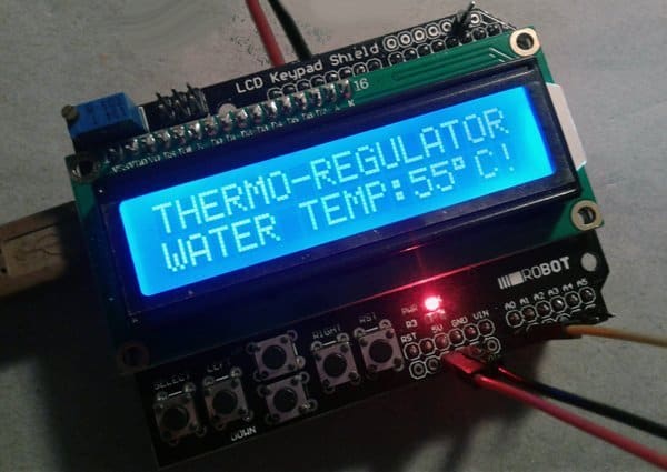
Often testing/using analog sensors with Arduino I noticed some pretty discrepant numbers on each time. Sometimes introducing a small delay in the code can stabilize things a bit better but still weak analog signals from most sensors will make nasty oscillations. If you wanted to make your analog sensor’s data as steady as possible, note that filtering is a proven method to eliminate some of the unwanted signal to leave a smoother result. Averaging is the most popular filtering algorithm, and it’s one of the easiest ways to filter noisy data by averaging i.e. sum up multiple measurements, then dividing the total by the number of measurements added together. See the code snippet used in a do-it-yourself thermometer project to calculate an average temperature measurement.
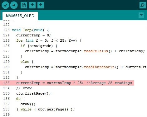
(for full project details, go to – https://www.electroschematics.com/14354/handheld-digital-thermometer-using-arduino)
Certainly, there’re other filters like the exponential filter which is, in fact, a recursive filter. We’ll try to cover this more in a succeeding article. Please stay tuned until it gets light!