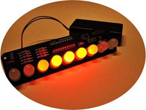
This is the simple way to play with a Larson Scanner. Just buy a Larson Scanner kit like the one shown above and start up the system. This quite popular open-source hardware 9-LED Larson Scanner from Evil Mad Scientist is based on a small microcontroller, the ATTINY2313V-10PU. Want to see what’s really behind this pretty nice piece of funny electronics? This page is the central documentation site for the Larson Scanner kit from Evil Mad Scientist https://wiki.evilmadscientist.com/Larson_Scanner.
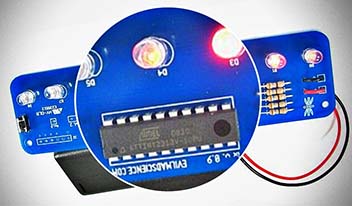
The circuit of this Larson Scanner kit is simple enough to understand by a novice. It’s just a microcontroller, 9 LEDs, 9 current limiting resistors to prevent the LEDs from burning out, and a button. It usually takes about an hour to complete the build from start to finish. Besides, because the project is open source, if you decide to, you can get into the code and modify its functionality.

According to Wikipedia, the Larson Scanner is named after Glen A. Larson, who produced the Battlestar Galactica and Knight Rider series, and is responsible for introducing scanning red light 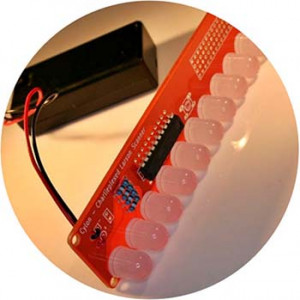 effects to the sci-fi TV viewing population of the 70s and 80s. (http://en.wikipedia.org/wiki/Glen_A._Larson).
Well, now to my most recent fun project which is a quick take on the classic Larson Scanner – the Arduino Larson Scanner. While this is a simple and fun project, you can of course elaborate upon the basic theme to talk about more advanced constructs. That’s pretty much my goal with this entry-level Arduino hobby electronics project. Okay, let’s get started!
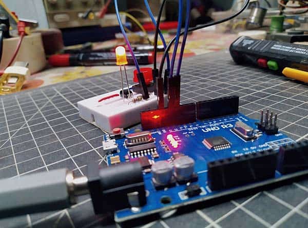
The hardware part of my Larson Scanner is a ridiculously simple and easy to build electronics assembly as it’s centered on an Arduino Nano microcontroller. Apart from the Nano board, you only need 8 ultrabright 5mm red LEDs, 220Ω (or 270Ω) ¼ w resistors, and a 10KΩ trimpot/potentiometer. The common 6F22 9V battery can be used to run the Nano Larson Scanner smoothly (or you can use any other appropriate dc power source you’ve in hand). Following figure depicts the wiring diagram of the Nano Larson Scanner v1.
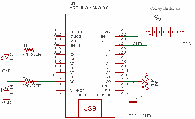
It’s worthy to take notice that since you’re running the LEDs from the same power source as the Arduino, the changes in current draw by the LEDs is probably causing high noise levels on the supply and AREF inputs. This is quite natural because the code responds significantly to changes on the trimpot/potentiometer and even while you’re not touching the knob, the readings might change anyway. So, how do we cope with this? To reduce the measurement noise, you can try including a simple low-pass filter (LPF) in the software. Another quick ‘hard’ way is to place a small capacitor (C1) from the wiper of the variable resistor to ground but as close as possible to the analog input pin (A0). Somewhere around 100nF to 470nF should suffice (you can try this method and comment back).
Certainly, this is an easy way to build and run a Larson Scanner using an Arduino, with the added option of setting the scanning interval with a standard variable resistor. Since I decided that a Larson Scanner with eight bright LEDs was enough, here’s the code v1 (Arduino Sketch) for that. I really want to advise you that you’ll tweak this crude code deep as it helps to land up with a more beauteous Nano Larson Scanner.
int ledArray[] = {9, 8, 7, 6, 5, 4, 3, 2};
int count = 0;
int timer = 50;

void setup() {
  for (count = 0; count < 8; count++) {
    pinMode(ledArray[count], OUTPUT);
  }
}
void loop() {
  for (count = 0; count < 8; count++) {
    digitalWrite(ledArray[count], HIGH);
    delay(timer);
    digitalWrite(ledArray[count + 1], HIGH);
    delay(timer);
    digitalWrite(ledArray[count], LOW);
    delay(analogRead(0) / 8);
  }
  for (count = 8; count > 0; count--) {
    digitalWrite(ledArray[count], HIGH);
    delay(timer);
    digitalWrite(ledArray[count - 1], HIGH);
    delay(timer);
    digitalWrite(ledArray[count], LOW);
    delay(analogRead(0) / 8);
  }
}
Once you have readied everything up, take a tea break then double-check your craft. And once you are satisfied you set everything aright, fire the mesmeric eye up!
In truth, there’re a couple of versions of the Nano Larson Scanner code. The next is the classic (v2). I just want to have my LEDs controlled by the microcontroller and not to control it. You can use the first hardware setup (without the trimpot) for that one too. However, you must program your Arduino Nano with the following code (v2).
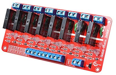
The first one (v1) is actually prepared as a bit ‘advanced’ version to drive eight AC230V incandescent bulbs thru a 5V/ 8-channel solid-state relay (SSR) module, you can use it as a pocketable Larson Scanner, though. And, the second (v2) is the real ‘classic’ version i.e. a near-close replica of the celebrated Larson Scanner (a series of lamps that lit up from left to right and then back again) which lets you house the whole build inside a compact sturdy enclosure that’s somewhat transparent and waterproof. Remember, the enclosure must be ‘deep’ enough to house the Arduino Nano board with all LEDs and battery pack(s).
The 8-channel SSR module looks like this (https://robu.in/product/8-channel-5v-solid-state-relay-module-board-omron-arduino).
const int ledCount = 8;

int ledPins[] = { 2, 3, 4, 5, 6, 7, 8, 9 };

void setup() {
  for (int i = 0; i < ledCount; i++) {
    pinMode(ledPins[i], OUTPUT);
  }
}

void loop() {
  for (int i = 0; i < ledCount; i++) {
    ledBarDisplay(i);
  }
  for (int i = ledCount; i > 0; i--) {
    ledBarDisplay(i - 1);
  }
}

void ledBarDisplay(int ledOn) {
  for (int i = 0; i < ledCount; i++) {
    if (i == ledOn)
      digitalWrite(ledPins[i], HIGH);
    else
      digitalWrite(ledPins[i], LOW);
  }
  delay(100);
}
Currently, I’m using Arduino IDE 1.8.13 on my Windows 10 computer. In order to get my old Arduino Nano v3 clone programmed, I set the menu items as “Tools → Board: → Arduino Nano” and “Processor: → ATmega328P (Old Bootloader)”.
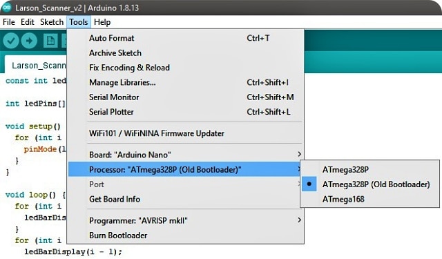
Note that Nano boards from January 2018 have the new bootloader, while boards manufactured before that date have the old bootloader. If I understood correctly, there’re two significant differences between the old (ATmegaBOOT) and new (Optiboot) bootloaders. First, the new bootloader will not go into an endless loop after a watchdog reset. Second, the new bootloader expects the upload communication at 115200 baud (This is the reason why the old Nano v3 boards don’t work with the Tools → Processor → ATmega328P selection and vice versa). I know I (you too) can certainly upload the new bootloader to a Nano v3. Related link https://www.studiopieters.nl/arduino-bootloader-upgrade/
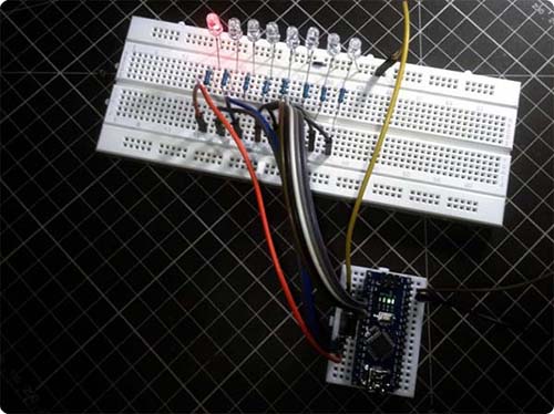
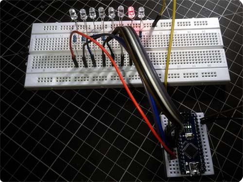
Oh, let’s get back to the prime topic. This project (v1 and v2) works quite well but has not passed the prototype stage yet. It’s still built on a breadboard platform (it helps me to track errors and modify the design at ease). Below you can see my quirky test set up of the Nano Larson Scanner v2.
That’s all. Now build your own Larson Scanner and fire it up. It’ll work. Have fun!