When you want to build a standalone Arduino project, the first thing to consider is how to power it once the setup is disconnected from the computer’s USB port. First off, it’s good to note down that, in addition to the USB power supply the external power sources for Arduino are linear/switching power supplies, and primary/secondary batteries of various types. Luckily, the Arduino’s internal power supply circuitry is designed to do the right thing no matter which recommended power source is plugged in!

In this article, you can see an in-depth explanation of Arduino UNO’s power supply subsystem. Well, now you can go through this link to access that great post https://technobyte.org/arduino-uno-power-supply-arduino-hardware-core/
Arduino & 3S LiPo Battery!
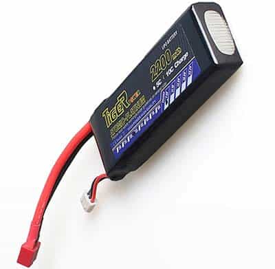
Usually, I’m using 3S LiPo batteries to power my standalone Arduino projects. And, as the voltage of the battery varies with use, I would always wire it through the Vin header. Obviously, this simple trick allows the onboard voltage regulator circuitry to stabilize the microcontroller power rail aright thus prevents the battery from frying Arduino’s sensitive electronics.
Powering the Arduino UNO board thru the Vin female-header is basically the same as using the DC barrel jack. It’s clear from the official schematic that the only difference is the polarity reversal protection diode. The commonly recommended input voltage here is 9VDC which is in between the recommended minimum and the maximum input voltages (7-12V).
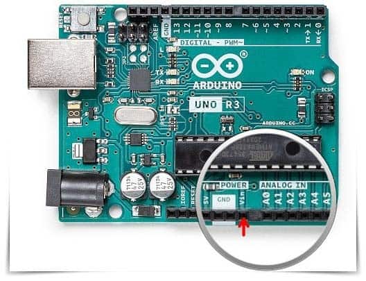
At this point, note that the voltage input header and the dc power jack are both connected to the same voltage regulator circuitry, which can take in voltages between 7-12V and convert them into stable 5V demanded by the AVR microcontroller.
Warning! While powering your Arduino UNO thru the Vin header, reverse polarity of the Vin/GND power connection will kill your Arduino board. This is because there’s no reverse-voltage protection on voltages applied to the Vin header.
At this point, note that Arduino UNO Rev3 Schematic https://content.arduino.cc/assets/UNO-TH_Rev3e_sch.pdf
Why you need a Battery Status Monitor?
A battery status monitor is a must-have in this application to prevent deep-discharge of the lithium battery and the brownout of the microcontroller. If so, the system can then display a low-battery warning message or switch itself off when the battery falls below the minimum required input voltage.
Quick Note: For a common 3S LiPo battery (11.1V nominal), the maximum voltage at full charge is around 12.6V, and the minimum voltage below which it should no longer be used is 10.2V. LiPo Battery Guide https://www.genstattu.com/bw/
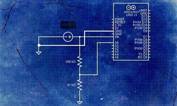
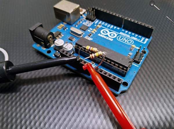
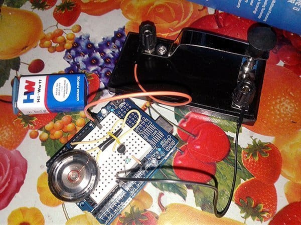
An easy way to implement this is to make the microcontroller monitor its own battery status by using one of the analog input pins. The hardware setup I use to monitor the battery status is shown below. As you can see there, it’s nothing but a couple of resistors wired as a potential divider!
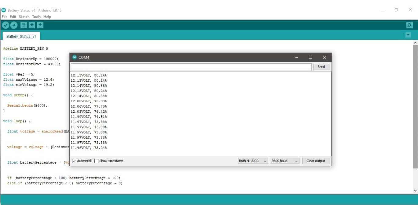
This is a simple piece of code useful for monitoring the battery percentage on the Arduino setup.
#define BATTERY_PIN 0 //A0

float ResistorUp = 100000; //100K
float ResistorDown = 47000; //47K

float vRef = 5; // VREF (Default)
float maxVoltage = 12.6; // Vmax
float minVoltage = 10.2; // Vmin

void setup() {

  Serial.begin(9600);
}

void loop() {

  float voltage = analogRead(BATTERY_PIN) * vRef / 1024.0;


  voltage = voltage * (ResistorUp / ResistorDown + 1);


  float batteryPercentage = (voltage - minVoltage) / (maxVoltage - minVoltage) * 100;


  if (batteryPercentage > 100) batteryPercentage = 100;
  else if (batteryPercentage < 0) batteryPercentage = 0;


  Serial.print(voltage); Serial.print("VOLT, ");
  Serial.print(batteryPercentage); Serial.println("%");
  delay(1000);
}
The serial monitor output you’ll get from the system then looks like this:
Note that this setup can monitor the dc voltage feed through Arduino’s dc jack as well but there’s a one-diode voltage drop (0.5V to 0.8V) to consider when tweaking your code.
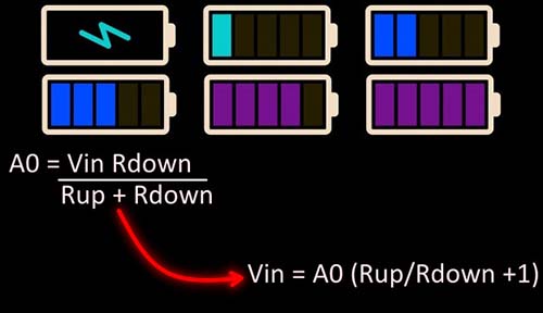
Nevertheless, the ratio of the resistors should be chosen so that the voltage at the middle point (A0) of the potential divider is below 5V when the battery voltage is at its maximum.
Here, the basic formula A0 = Vin x Rdown / Rup + Rdown, can be rearranged to measure the battery voltage Vin. So, Vin = A0 x Rup + Rdown/Rdown, or Vin = A0 (Rup/Rdown +1)!
Okay, that’s all for now. Next is your turn to develop this basic concept further to make it suitable for a real-world project. Remember – do what feels right for you. And when you feel ready, make it!
Author’s Update:
Now I think the basic formula will confuse some readers. Sorry, it’s prepared in a haste!
Actually, the Rup is the 100K Resistor & Rdown is the 47K resistor when referring this image https://www.codrey.com/wp-content/uploads/2021/08/Arduino-Battery-Status-Monitor-Hardware-Setup-v1.jpg
Thanks to many social media followers for drawing my attention to this 👍