 Equipped with a magnetic door sensor, this entryway light controller automatically detects the status of the gate or the entryway barrier to control the entryway light. Moreover, day/night status is monitored by a photosensor so the controller does not wake up when it’s not needed. Simply, the entryway lamp lights up only when you expect it to!
Circuit Diagram & Description
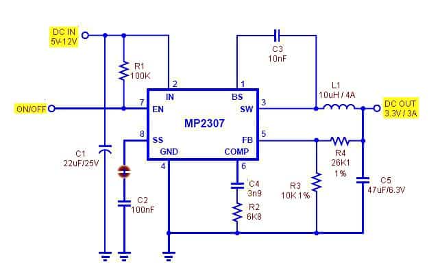
This is the circuit diagram of the AC230V automatic entryway light controller:
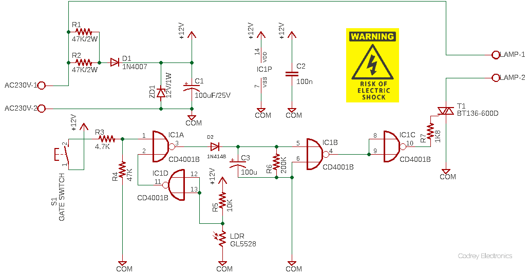
This automatic entryway light controller is designed as a standalone unit with its own inbuilt power supply. The low-current power supply circuit is a tricky AC230V to DC12V step-down voltage regulator built around components R1, R2, D1, ZD1, and C1. The additional 100nF capacitor (C2) must be wired as close as possible to the Vcc and Gnd (Pin 14 & Pin 7) of the CD4001B CMOS Quad 2-Input NOR Gate (IC1).
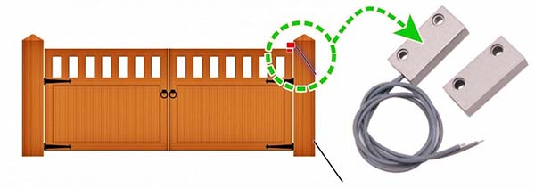
The gate switch (S1) is a magnetic door switch which is in fact a small reed switch and magnet assembly specifically designed for door/window security applications. One piece of the switch assembly (the encapsulated reed switch) can be mounted on the gate frame while the other (the encapsulated magnet) to the gate itself (see below figure). When each piece of the setup comes close to each other (<20mm), the internal reed switch closes, and when it is separated from each other, the reed switch opens thus triggers the connected device. Note that the magnetic door switch happily accepts a maximum voltage of up to 100V at 500mA. Further, since it is housed in durable ABS plastic and, comes with suitable screws, it can be attached to most surfaces at ease.
As clearly depicted in the circuit diagram, the gate sensor switch is connected to one input of the first gate (N1) of CD4001B (IC1) while the output of the GL5528 photoresistor (LDR) is wired to the second input of gate N1. Note that the photoresistor’s output is inverted by the fourth gate N4, and the LDR has a 10K pull-up resistor R5 to set the light/dark detection threshold. In deciding on the value of the pullup resistor in the voltage divider with the photoresistor, you need to take into account the range of light levels you want to measure. Frankly, there’s a trade-off that you will have to decide upon!
In operation, whenever both inputs of N1 sees a logic-low state, its output jumps to a logic-high state, and thus operates the BT136-600D triac (T1) thru next two gates (N2-N3) of IC1. Even if the input state of gate N1 is reversed, T1 remains fired for a finite period determined by the RC time constant (R6-C3) – that means the entryway light/lights wired through T1 stays on for circa 15-20 seconds.
The BT136-600D (https://www.mouser.in/datasheet/2/848/BT136-600D-1666873.pdf) is a sensitive gate four quadrants general-purpose triac intended to be interfaced directly to microcontrollers, logic integrated circuits, and other low-power gate trigger circuits. Since the “RMS on-state current” of T1 is 4A, it can happily drive most Ac230V entryway lamps, an appropriate TO-220 heatsink is recommended though. For small loads or very short duration load current, it might be okay to operate the triac in free air. In this case, however, it would be fixed to a heatsink. The main methods of clamping the triac to a heatsink are clip mounting and screw mounting. Beware! The heat sink directly touches the live terminal (MT2) of the triac!
Construction & Test Run
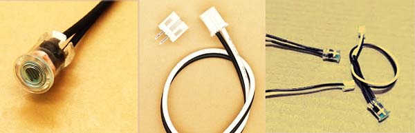
The entire electronics can be assembled on a general-purpose prototype board, preferably with a good quality socket for IC1. It would be good to employ a 2-pin JST connector for the gate switch, and a WAGO™ PCB terminal block (2-Pole) for the entryway lamp(s), by rigidly soldering them on the circuit board. Also, go for the waterproof version of the GL5528 LDR (see below figure) if it is easily available for purchase.
While testing the assembled circuit board, make sure that your build is working aright in both situations i.e., when the LDR is in full light and in complete darkness. Do not use your finger or hand to mask it!
Remember that the power supply part of this design is a simple transformer-less dc power supply certainly without any isolation. There is a greater risk for dangerous shocks someone won’t soon forget. Yikes!
Moreover, even though only a minimal amount of power is used to maintain the electronics, the power resistors might become red-hot (plenty to burn your fingers) during an active state, so give them ample free space in and around.
After initial testing, place the entire assembly inside the waterproof transparent/translucent project box. If so, the photoresistor can see the outside world better. If you opted for the regular opaque project box, then fit the photoresistor on its outside (and make sure the setup is shockproof and waterproof).
Components List
- IC1: CD4001B
- T1: BT136-600D
- D1: 1N4007
- D2: 1N4148
- ZD1: 12V (1w)/1N4742A
- R1-R2: 47K (2w)
- R3: 4.7K ¼ w
- R4: 47K ¼ w
- R5: 10K ¼ w
- R6: 200K ¼ w
- R7: 1.8K ¼ w
- LDR: GL5528
- C1-C3: 100uF/25v
- C2: 100nF
- S1: Magnetic Door Switch (MC-38)
Author’s Note
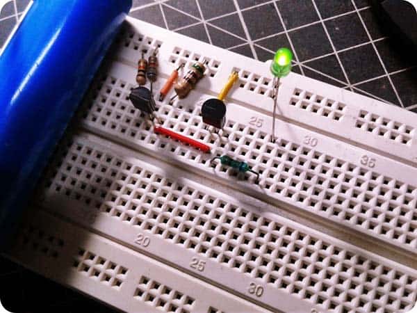
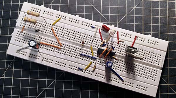
Following the usual practice, I built my prototype on a regular breadboard and tested it, and it worked as expected. Below is a cursory snap of my breadboard that I took just before the final lab test.
Later, I finished the project with a new circuit board and acrylic enclosure and installed it on my neighbour’s entryway for a trial run. It still does its duty well!