 I get a lot of requests to publish simple clap switch projects even in this wireless and internet of things era. Of course, there are countless projects available across the web, and hobby/educational kits are also available for cheap. Even so, I respect the needs of my readers and followers. So, in this post I want to share some random thoughts about clap switch design ideas. Okay, let me write something useful for you!
Not joking, the easiest method to make a clap switch is to buy a do-it-yourself kit from a trusted seller. If so, all you then needed is only a soldering iron and enough spare time to do the soldering work well. For example, below you can see a clap switch kit sold by the famous Chinese online store – IC Station (http://www.icstation.com).
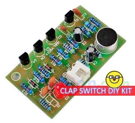
Surprisingly, this hobby kit is designed with a few transistors instead of an IC. However, its output does not have an onboard relay to control external loads – only an LED to indicate clap function instead. The circuit has two main stages – first one is a microphone preamplifier circuit and the second is a bistable multivibrator circuit. This 4-transistor kit is designed to be powered by 5VDC supply. According to the seller’s description, frequency response of the microphone circuitry is restricted to 3kHz (I am a little confused about this foggy description).
I know many of you may not be interested in following this shortcut. So below is an Arduino concept!
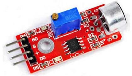
In order to build the Arduino clap-operated switch, you need one “Sound Detection Sensor Module” (see below).
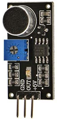
In this Chinese module, sound signal is detected by an electret microphone capsule (https://en.wikipedia.org/wiki/Electret_microphone) which is fed into the LM393 voltage comparator (https://www.ti.com/lit/ds/symlink/lm393-n.pdf). The sound level setpoint can be adjusted via an onboard trimpot. When the sound level exceeds the preset threshold, an LED on the module illuminates and the output goes low (H → L).
This is the specification of the above-shown sound detector module (copied from the seller’s page):
- Operating voltage: 3.3V-5V
- Outputs digital switching output (high and low level 0 and 1)
- Operating current (Vcc=5V): 4-8mA
- Microphone sensitivity (1Khz): 52-48dB
- Microphone Impedance: 2.2KΩ
- Microphone Frequency: 16-20Khz
- Microphone S/N ratio: 54dB
- Signal output indication LED
- Single-channel digital signal output
- Outputs low level and the signal light when there is sound
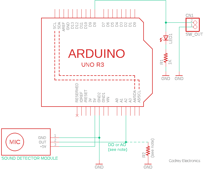
This is the proposed Arduino hardware wiring diagram:
And, here is the code (Arduino Sketch):
/*
 * Simple Arduino Clap Switch (v1)
 * Key Hardware: Arduino Uno R3 & Sound Sensor Module
 * Read the article to get the full project details!
 * Author: T.K.Hareendran/06-2021
 */
long long int last_states = 0;
void setup() {
  pinMode(8, OUTPUT); // Switch Output = D8
  pinMode(A2, INPUT); // Sound Input = A2
}
void loop() {
last_states = last_states << 1;
//if(analogRead(A2) > 500){ // For AO Input
  if(analogRead(A2) < 500){ // For DO Input (See Notes)
  if(last_states == 0){
    digitalWrite(8, !digitalRead(8));
  }
  last_states++;
}
delay(20);
}
Here, both the Arduino hardware and software are configured in a way that it can be modified to work happily with almost all Chinese sound detection sensor modules. Usually, the sound detection sensor module has three connection terminals (+5V, GND, OUT) but you can also see modules with four connection terminals (DO,+, G, AO) where the fourth connection (AO) is the analog signal output.
Yes, this is certainly not a perfect setup, and you need to do some tinkering to make the final version more practical and effective, but I think this is good enough for us at the moment. I am not a seasoned coder. So, if you find something that is not in the right way, feel free to correct me!
Looking at my schematic again with fresh eyes you can clearly see an unknown resistor R2 at the analog input point. Actually, that pulldown resistor is not very important, but there is nothing wrong with adding it there. Anyway, make sure that R2 isn’t too low otherwise it might load the inputted signal you are trying to detect/measure. I was going to go with a 100K (or higher) resistor. Look, here we tailored the analog input A2 to sense both variable range input (analog signal output from the module) and high/low input (digital signal output from the module).
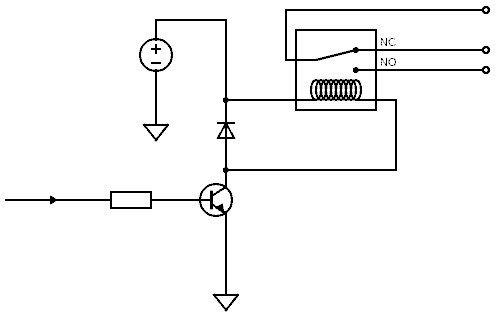
Moreover, output of the Arduino clap switch (D8) is used to turn a single LED (LED1) on and off but that is just for debugging tasks. You should extend the D8 output, through the 2-pin connector CN1, to an appropriate electromagnetic relay to clap-control your electric loads like lamps, fans, etc.
A word of caution: Don’t tinker with fatal mains voltages unless you’re really sure about what you’re doing!
So, you would need to have an NPN transistor, a resistor, and a flyback diode for the electromagnetic relay intended to control the desired load. Really, any small BJT with a minimum hFE of say 50 to 100 could be used – it will however depend how much current you’re willing to draw from the concerned I/O pin, how much current is required to energise the relay’s coil, and the actual hFE of the transistor picked by you, since they vary wildly and the current gain (β) could easily be significantly more than the stated minimum.
The flyback diode in the circuit is there to conduct the current generated by the de-energising relay coil back across the relay coil, allowing the power to dissipate more gradually, thus heading off an accidental voltage spike.
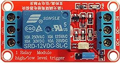
Or you can try a pre-made Chinese relay module that has an active-high trigger input option.
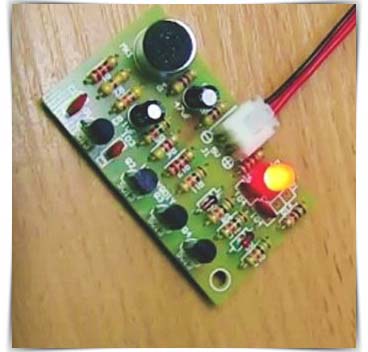
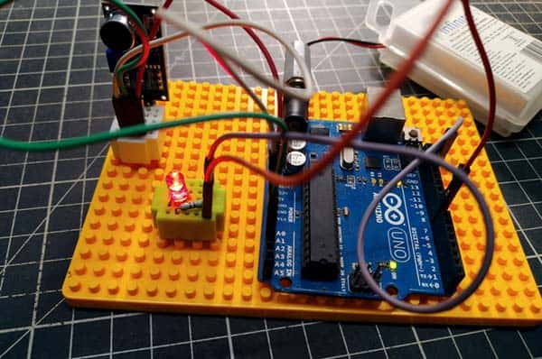
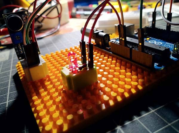
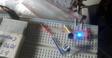
Finally, below you can see snapshots of my quick prototype used in preparing this tutorial.
As clearly mentioned in the title, this setup can also be used as a ‘tricky’ blow switch! A blow switch is ideal for those who have very limited movement and allows the user to blow into the mouth piece (microphone) to activate a panic alarm. Next time I will describe ways of using inexpensive electronics components to make a dedicated blow switch for nurse call systems.
Voila! That’s the end of today’s post. You can now go ahead and use this adaptable idea for your real-world applications. Enjoy!
Author’s Note:
The threshold values in the code can be tweaked to trigger an appropriate action when a certain sound level is reached. For example, when the amplitude of the sound crosses a predefined threshold (500 now), the code activates D8 I/O of the Arduino in this setup.
See, when the ADC reports 500, voltage appeared at the Arduino analog input is around 2.45V (10-Bit ADC & 5V).
Further, this circuitry cannot distinguish between a gentle handclap and a loud noise from another source. That’s quite natural. However, you can modify the basic code by adding an algorithm which take care of the processes of detecting/evaluating claps, resetting counters & states, and toggling the I/O, etc. I won’t get into the details now, but you can see an improved design later!