Often you’ll need a simple pulse width modulation generator circuit to test or run small dc lamps and motors in your electronics projects. There’re ways of creating cheap and practical circuits at home, and today we’ll be focusing on the build of a junk box 555 PWM generator. What is more, there’s a small surprise at the bottom of this post!
Circuit Diagram
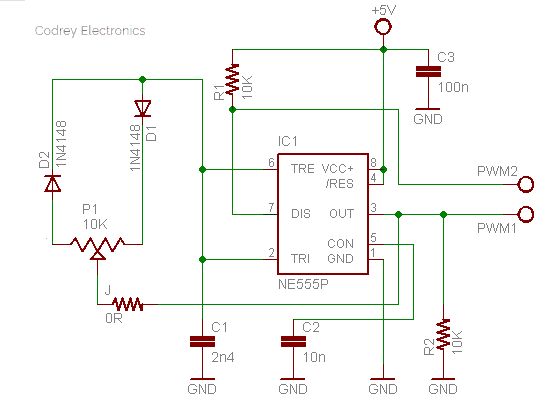
First let’s start off with the practical circuit diagram. As stated above, the 555 timer is used here in this circuit as the core of the PWM generator, as well as to perform some less conventional duties.
Design Description
In the circuit, NE555P (IC1) is configured as the conventional basic astable multivibrator (AMV) but with a slight modification. The modification includes a 10K multiturn-trimpot (P1) and a pair of 1N4148 diodes (D1 & D2) to steer the mark-space ratio. When the trimpot is at the maximum setting, the output at pin 3 of IC1 is predominantly high, with only narrow pulses to zero. When at the minimum setting, the output is mostly at zero, with narrow positive pulses. This is because when the trimpot is at its maximum, it takes much longer to charge C1 (2n4) than to discharge it, so the output must spend most of its time at Vcc (close to 5V). The reversed applies when the trimpot is at its minimum. The minimum and minimum duty-cycle can be changed by altering the value of the 0R resistor (J), if necessary. You must be aware of the inherent limitation of 555 timer that when its output is high, it will typically be somewhere between 1.2V and 1.7V lower than the supply voltage (Vcc), counting actually on the current drawn from the output (pin 3).
The 2nd PWM Channel
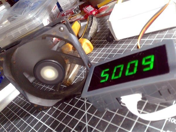
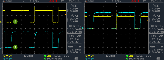
The given circuit configuration will give you a typical signal output (PWM1) through the output (Pin 3) of IC1. As observed in my dirty breadboard prototype, the PWM frequency is around 27kHz (maximum) with a variable duty cycle that shifts approximately from 9% to 99% (see the table below).
| Trimpot (P1) | Minimum | Maximum |
|---|---|---|
| Output (Pin 3) | ~ 300mV/27kHz/9% | 3.7V/6kHz/99% |
Nevertheless, you can see an ‘unusual’ second channel (PWM2) sprang up from the same PWM generator circuitry! It’s merely a close replica of the first channel (PWM1) but taken directly from the ‘discharge’ terminal (Pin 7) of IC1.
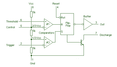
In the 555 timer IC, the discharge pin 7 is connected internally to the collector of the discharge transistor, and when the output pin goes low the transistor turns on. Note that pin 7 is open collector, and its transistor is turned on by the same flip-flop that controls the output at pin 3. Although Pin 7 has the same logic state as pin 3, pin 3 has an output buffer that can sink and source ‘strong’ current while pin 7 can only sink ‘faint’ current to ground. It would then also require one pull-up resistor (see the internal diagram).
Needless to point, you’ll find that the second channel output (PWM2) get ‘inverted’ if you probe for it across the 10K pull-up resistor (R1). Likewise, as can seen in the random oscillograms (shown below), it’s relatively a bit high in amplitude. But for now that’s great!
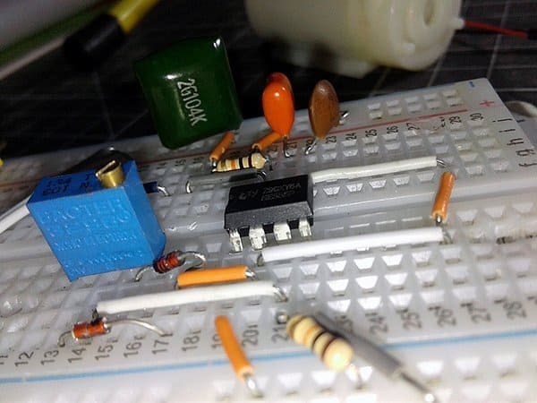
I have to say this is a fun project (more than just a purely educational exercise), but you can do a number of modifications to build your own cheap and cheerful dual-channel PWM generator(s) using discrete components you already have in your dusty junk box. Yes, it can be done if you’re ready to accept some limitations.
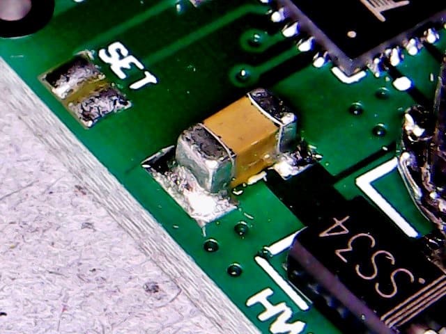
Below is a lowly picture of the junk box PWM generator circuit built on a mini breadboard. In my particular build, I used a regulated 5V breadboard power supply which fits nicely on the edge of the mini breadboard.
Now what else can this be used for?
The way it works is not different from a basic 555 PWM generator, except that it has an extra ‘mirror’ PWM channel. To be useful, the primary channel output (PWM1) can normally drive a mosfet to run an external load. Besides, the second channel (PWM2) can easily drive another external load but with an appropriate additional circuitry. Admittedly, the presented design is largely conceptual – it’ll work , but is not an optimal one.
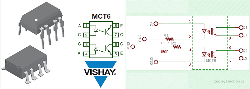
Using the PWM channels to drive external circuits is where I strayed from the pack. Instead of using those signal channels directly, I opted to try one quite common dual-optocoupler MCT6 rendering a pair of galvanically-isolated PWM channels. The following image shows a basic wiring diagram for the MCT6 optocoupler which is a great optocoupler (from Vishay) especially designed for driving medium-speed logic, where it may be used to carry off unwanted ground loop and noise problems. For technical queries, contact: [email protected]. The resultant ‘free-hanging’ outputs of the MCT6 can be used later for intended PWM applications as desired one (non-inverted output and one inverted output – if wired with pull-up resistors).
Pros and Cons
The 555 timer chip has been with us as of 1972! There are numerous manufacturers and many different part number prefixes and suffixes. Obviously certain Chinese versions has some noted anomalies that probably won’t result in a serious trouble to you I hope.
Back to my ‘odd’ design, the setup offers two PWM output channels at the same time so you can use the ‘default’ one (Pin 3) or the other (pin 7) comfortably. As mentioned previously, with a 5V power supply, you’ll get a maximum of 3.7V level signal through the normal output pin 3, but around 4.9V through pulled-up pin 7. However, with the addition of an optocoupler at the output, you’ll get much more freedom to tweak your own signal levels because of the galvanic-isolation (and open-collector/open-emitter outputs) provided by the optocoupler. Give it a good try, and let’s know about that. On the other side, trying to get both frequency and pulse width control doesn’t really work here. That means the circuit won’t allow you to set the frequency and then alter the duty cycle – you can set the duty cycle and the frequency is determined by that. For a little project in queue, I don’t need to have super tight control over the frequency, as I’m more focused in the duty cycle range, and that’s why this design.
Finally…
A Google search of the keyword “555 PWM” will return over 45,30,000 results! If you want more information, do download this good old (1972) reference guide (in PDF) at the start. http://www.rfcafe.com/miscellany/cool-products/Signetics-555-556-Timer-1973-Databook.pdf
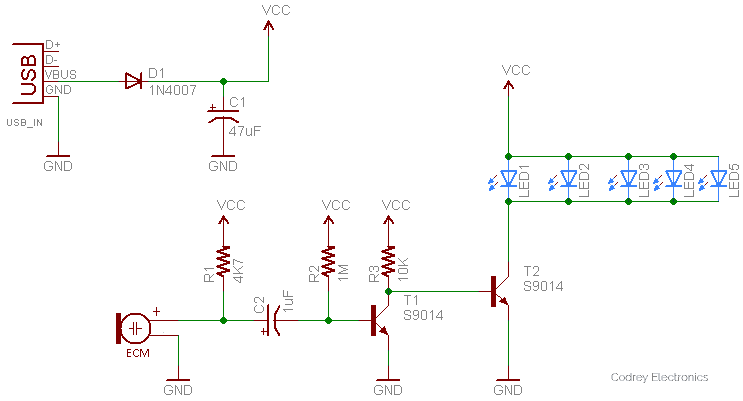
Festival season is around the corner, so here we’re giving the novel design idea of a sound-controlled LED festival lights (adaptation of a Chinese design – untested). After successful construction, simply place your final build close to the loud speaker of a mobile phone, music player, or television, and then play your favorite music to see a bunch of blue LEDs start dancing in tune with that!
Well, Happy Xmas and New Year Greetings to All…See you in Next Year!
[no_toc]