Simple flame supervisor is nothing but a little flame status monitor. The theme of this play is to build a cheap device to provide an alert when the flame under supervision runs out unexpectedly. Admittedly there’re countless commercial flame-failure alarms available, but they usually work by sensing the temperature of the heat source. That wouldn’t handle the situation where the fuel is available but the flame extinguishes by chance. So, let’s start an easy walk around do-it-yourself ideas for poor man’s optical flame detectors!
Let’s set the key component
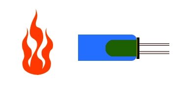
Since we’re building an optical flame sensor, as might be expected, the key part is one optical flame sensor. Certainly, we’re not going to buy a costly optical flame sensor from an overseas market because any generic infrared phototransistor alone can play the role well. Anyway, the phototransistor must have a suitable spectral bandwidth, preferably in 760-1100nm range. So the quick pick now is a 5mm LED-shaped, high-speed, high-sensitivity, NPN phototransistor – the YG1006 (https://www.rhydolabz.com/documents/29/YG1006_Datasheet.pdf). Okay?
Quick preparation of the sensor part
As can seen in the below schematic, the YG1006 phototransistor needs just two support components to give an ‘analog’ output representing the intensity of the probed flame.
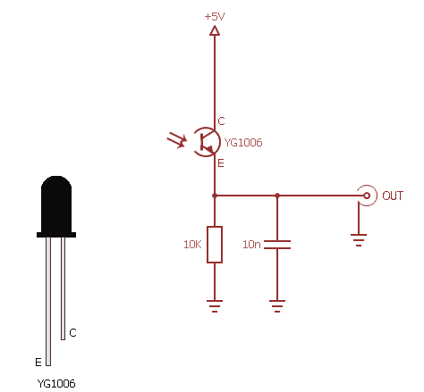
Cool! Isn’t? However, note that the flame sensor with a probe angle of 60 degrees is sensitive not only to a flame but also to the ordinary light. Naturally, the final analog output will be influenced greatly by the intensity and distance of the probed flame/light source. We can ofcourse feed analog signal output of the flame sensor part directly to one analog input port of an Arduino so that the clever microcontroller can do the rest of the flame supervision job. But it’s a pointless move at this time – keep your lovely Arduino intact for upcoming serious electronics projects!
Anyway interested hobbyists can experiment with this simple code tailored for Arduino Uno. The code reads our flame sensor value through one analog input (A0) port of Arduino.
int flameSensor = A0; // A0 as input to receive flame sensor’s output signal
int blinkOut = 13; // Visual indication by onboard LED @ D13
int Value = 0; // Variable to store the flame sensor value

void setup() {
  pinMode (blinkOut, OUTPUT);
  Serial.begin(9600);
}

void loop() {
  Value = analogRead(flameSensor);
  digitalWrite(blinkOut, HIGH);
  delay(Value);
  digitalWrite(blinkOut, LOW);
  delay(Value);
  Serial.print ( " Flame Value: ");
  Serial.println (Value, DEC);
}
How to build a discrete sensor interface?
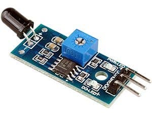
Obviously we need a simple electronics circuit here to get a digital (logic-high/low) output from our flame sensor. The quick and cheap method is the usage of a readymade flame sensor board/module coming from China. We can see two versions of the flame sensor modules based on YG1006 in the market – one has three pins (D0, Gnd, Vcc) and the other has four pins (A0, D0, Gnd, Vcc). Both modules, centered on LM393 IC, can be easily interfaced with Arduino and almost all other microcontrollers.
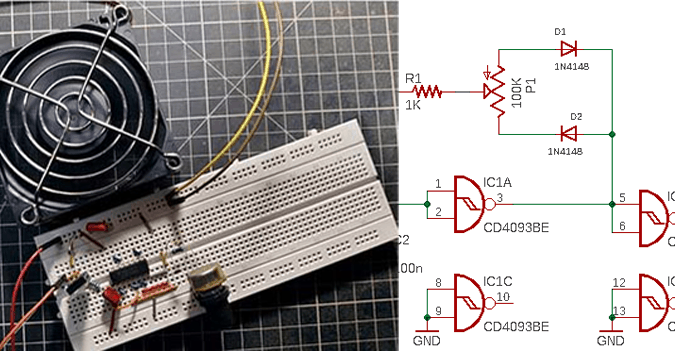
Another, perhaps a bit time consuming, method is to prepare our own flame sensor interface circuit with discrete components. Following is the canonical circuit diagram of a discrete flame sensor interface. You’re certainly welcome to modify the scheme. But I’ve found the current configuration works well.
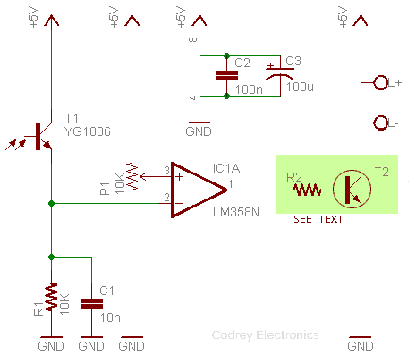
This scheme is based on one part of the LM358 op-amp (IC1A). The 10K trimpot (P1) sets the reference voltage at the non-inverting input (pin 3) of IC1. The YG1006 phototransistor (T1) and the 10K resistor (R1) shapes a voltage divider network. Simply, the driver transistor T2 turns on when there’s a flame failure. Resistor R2 sets the base current of T2, and, on paper, for a transistor with β>20, one 100Ω resistor can be used to get an output load current roughly 600mA. My quick test was carried out with one 2N2222A transistor (T2) and a 1K resistor (R2).
An important point – while adjusting the sensitivity of this circuit, do take a bit of care because LM358 is certainly not a rail-to-rail op-amp. The LM358 has a maximum allowable input voltage that’s less than Vcc by 1.5V at 25°C. So if the input voltage there is above 3.5V (5V−1.5V) then the output might be undetermined.
Returning to the first circuit (analog signal output), not often but it may become necessary to include a little interface circuitry between the sensor part and the additional electronics proposed to be connected simply to head off the ‘loading effect’. In principle, a unity-gain buffer is enough for the job. So I came up with the circuit below. Here, the output of the op-amp is fed back directly to its inverting (-) input, so the output tracks its non-inverting (+) input.
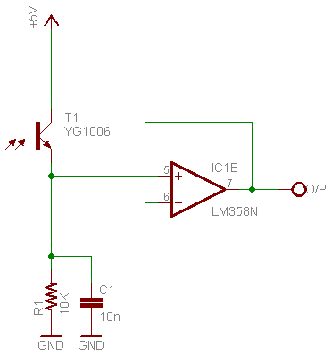
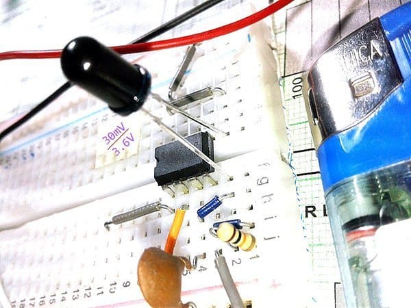
My prototype of this circuit when tested with candle flame (and cigarette lighter flame) delivered around 3.6VDC output (O/P) at 50mm distance in between the flame source and sensor part. Under the strong light of a 10W CFL, it’s around 30-40mV, however, a sensible hike in the output voltage (>2V) noticed when put the sensor part in the vicinity of a 40W incandescent lamp (bad luck)!
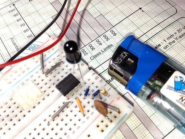
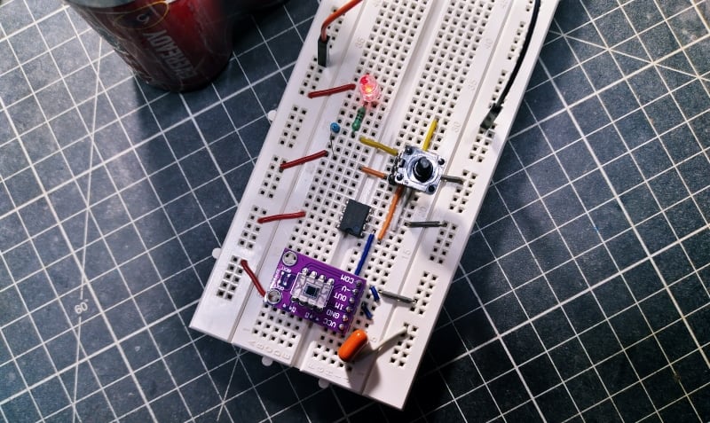
Later I used a small opaque tube to block off the flame sensor’s view to the side, that made it easier to pinpoint the direction of the flame.
Jumping to a conclusion
I think that I will halt my attempts for using the YG1006 as a flame sensor right here as it’s slightly responsive to other light in my surroundings. My next project in this sequel is an innovative burner alarm, possibly with wireless connectivity. Likely you may need to await a bit longer – the experiment is still in progress!