Very recently I wanted a couple of Hall-Effect Switches again for some random experiments, hence placed an order for a bunch of A3144 Hall-Effect Switch ICs. The online retailer quickly delivered the packet at my doorstep within two days through FedEx. However, at the time when the packet gets opened I was shocked – Yes, I got nothing but a few SS49E Hall-Effect Sensors instead of the prescribed parts!
Frankly, it’s not a big issue as I know that seller well and we’re maintaining a good relationship since our first deal. So I informed him about the trouble but he gently made a request for a delivery extension because of an inventory problem. Concisely I’d to wait here for two or more weeks to get them. As a last resort, I decided to build an ‘adapter’ circuit for the SS49E sensor to make one urgent design ahead. So, this article is to post my tryout here just in case somebody can benefit from it.
What’s the difference?
Wondered what’s the difference between the aforesaid Hall-Effect ICs? Okay, I’ll explain it in a few words. See, the A3144 is a sensitive Hall-Effect Switch, that means it has an open-collector output thus with a suitable output pull up, it can be used with Bipolar or CMOS logic circuits.
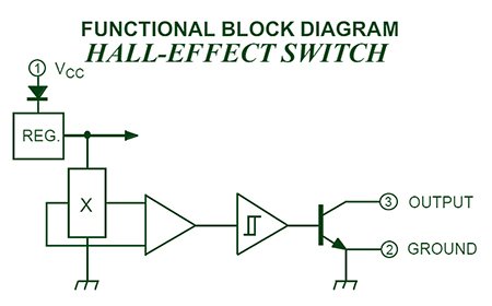
The unipolar switching characteristic of A3144 makes it ideal for use with a simple bar or rod magnet. The output of A3144 switches low when the magnetic field at the Hall element exceeds the operate point threshold (BOP). At this point, the output voltage is VOUT(SAT). When the magnetic field is reduced to below the release point threshold (BRP), the device output goes high. The difference in the magnetic operate and release points is called the hysteresis (Bhys). The built-in hysteresis allows clean switching of the output even in the presence of external mechanical vibration and electrical noise.
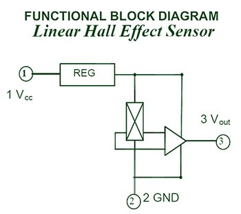
On the other hand, the SS49E is a Linear Hall-effect sensor that’s operated by the magnetic field from a permanent magnet or an electromagnet. The linear sourcing output voltage (Vo) is set by the supply voltage (Vcc) and varies in proportion to the strength of the magnetic field. The typical quiescent output voltage is 2.5V, the maximum output voltage is 4.2V (B=1500G), and sensitivity (△Vout) is 1.8mV/G at 25℃.
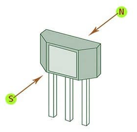
It’s worthy to noticing that a Hall-Effect IC changes/varies its output in response to the close proximity of a magnetic field. Usually, the branded surface of a Hall-Effect IC responds to the South Pole (S) of a permanent magnet, whereas the unbranded surface shows a response to the North Pole (N).
So we need an adapter circuitry
It’s observed that the approximate quiescent output voltage of my SS49E sensor is 2.4V which raises to about 2.6V when a magnet pole is sensed by the sensor. The output voltage gets an uplift to 4.1V when the sensor sees a very strong magnetic field (and zero-gap between the magnet’s pole and sensor’s face). Seems good!
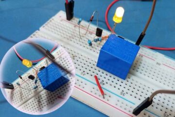
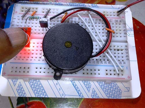
Anyway, this won’t let me to go further with my ongoing project as I strictly necessitate an open-collector output circuit, so jumped into the following design based on a handful of inexpensive electronics components. Even though it’s possible to use the LM393 IC at the core, I opted for the LM358 IC as it’s the only one at the ready. In the below scheme, one segment of the LM358 (IC1A) is wired as a voltage comparator configured to run on 5VDC. The 10K trimpot (P1) in the circuit can be used to ‘fine-tune’ the detection sensitivity/threshold value.
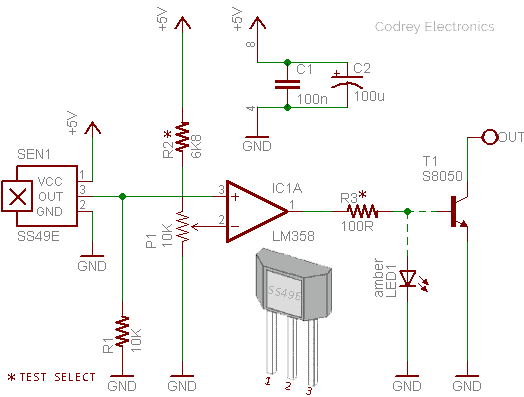
The LM358 is wired in a manner so that its output (Pin 1) will go HIGH if the voltage at the non-inverting input (Pin 3) exceeds the voltage level on the inverting input (Pin 2–Set by P1). If the voltage drops below the threshold, the output will go LOW. The output then handles the rest – we can either drive a common LED/Opto-Coupler through the output pin, or a small BJT/LOGIC-LEVEL MOSFET (to get an open collector/open-drain output). The demo is shown without the final driver stage – later it’s included (S8050 BJT) and tested successfully, though!
Ready for tweaking?
LM358 IC consists of two independent operational amplifiers (op-amps) designed specifically to run from a single power supply over a broad range of voltages. Since only one part of the IC is needed for one Hall-Effect Sensor, you can replicate the schematic (normally-low output) exactly to handle one more sensor. Or you can invert new circuit’s configuration to get a ‘reverse output’ i.e. a circuit with normally-high output from the second sensor.
Note that the LM358 has a push-pull output stage that will both sink and source current. As used here, an LM358 circuit with outboard transistors will drive a bit ‘heavy’ output loads. Anyway, in most practical circuits, there may be deviations from the ideal maths. In general, it’s often negligible, but for precision circuits you may need to add appropriate circuitry to improve the end result.
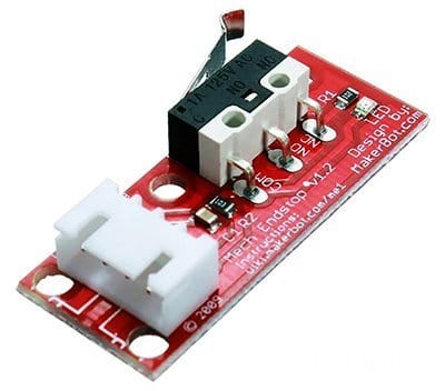
Furthermore, the circuit can also be configured to work as a better, Hall-Effect based endstop that allows you to adjust (via the trimpot), the distance limitedly at which the ‘on’ signal activates (the common mechanical endstop only provides an on or off signal). For example, thus you can replace the standard endstop of a 3D printer with the imrpoved electronic version to simply and quickly adjust the distance of the print-bed to the nozzle. Following figure portrays a mechanical endstop for RepRap.
That’s it for now, off to design a simple 3D printer accessory. Well, let’s see how well your builds work!