Morse code almost not need an explanation! Anyway simply note that it’s a telegraph code in which letters and numbers are represented by strings of dots and dashes (short and long signals). 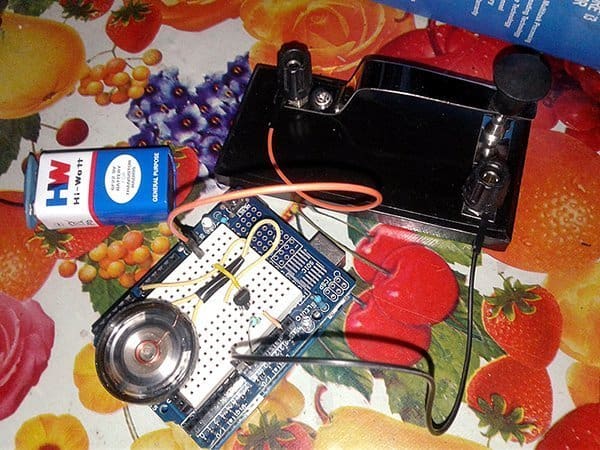 Learning and practicing the Morse code obviously requires a little code practice oscillator (CPO) to work with the Morse key. Luckily you can find a simple do it yourself project idea based on discrete components elsewhere in this Codrey website.
For a while now, I’ve had need of making a portable code practice oscillator, for my friendly neighbor, to be able to practice Morse code. Also, I have been asked by him several times for a quick design utilizing the Arduino microcontroller platform. To this end, I had got a good idea and eventually built an Arduino Morse Code Practice Oscillator that runs happily on a standard 6F22/PP3 9V battery. With this article, I try to share details of my little code practice oscillator project to you. I am happy if you got inspiration from the project idea presented here or learned something new.
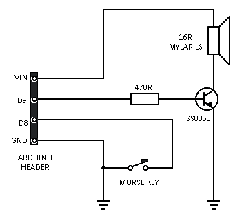
Apart from an Arduino Uno board, only one Morse Key (telegraph key), and a little bit of supporting electronics is all that needed to complete the project. The extra electronics circuitry is nothing but a single transistor based loud speaker driver. See its circuit diagram below:
Many Arduino projects have an idea that uses the Arduino function tone() to generate a sound. Typically a small loudspeaker is connected to an Arduino pin, either by a resistor or a coupling capacitor. While that idea works well for demonstrations, the use of a resistor or capacitor alone has certain disadvantages including low-volume tone output. A linear audio amplifier can make it louder, but at the expense of respective parts.
When you’re hooking up a loudspeaker to an Arduino as mentioned above, the reason for the feeble sound comes down to the fact that the digital out pins on AVR microcontrollers can only source (or sink) around 50mA. Most loudspeakers, including the small ones, might draw a lot more current than that, and without an ‘active’ circuitry in between you’d probably fry the pin on your microcontroller!
Note that the Arduino tone is merely a square wave repeated at the desired frequency, and it’s not very musical. So to make the tone output louder all that’s needed is a way to increase current through the loud speaker. And this can be done by the given extra electronics circuitry. Notice the positive rail connection to Vin header rather than the 5V header. This allows greater current than can be delivered via the Arduino itself.
The Arduino Sketch is prepared out pretty much simple as the hardware. When you run it you should hear tones when you press the Morse Key. Copy and paste the given code on the right into your Arduino. The code start by declaring variables for the input and output pins. The ‘val’ will be where it stores the state of the key input. The ‘keyTone’ is the frequency of the tone you will hear.
Give this a try and see how it goes. It’s certainly something to bear in mind, the 440Hz created a much more sweet tone for me. You may need to experiment to find a value that works in your own constructs. Don’t forget, the Tone() function can generate only square waves of fixed 50% duty cycle. And, the frequency value should be of minimum 31HZ and 65.535kHZ maximum as it’s the minimum and maximum frequency values that can be produced by AVR boards.
/*
Morse Code Oscillator v1
Another Simple, Adaptable, Arduino Project
Authored By T.K.Hareendran/2019
Published By codrey.com
*/

int morseKey=8; // Morse Key Input D8
int sounder=9; // Key Tone Output D9
int val=0;
int keyTone=440; // Key Tone Frequency 440Hz
void setup() {
pinMode(morseKey, INPUT);
pinMode(sounder,OUTPUT);
digitalWrite(morseKey,HIGH); // Weak Internal Pull-up Enabled
}
void loop() {
val=digitalRead(morseKey);
if (val)  noTone(sounder);
if (!val) tone(sounder,keyTone);
}
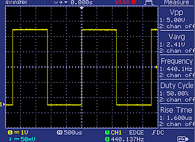
Here’s an oscilloscope picture of the ‘unloaded’ D9 output signal I’ve got with my code, worked excellent for me.
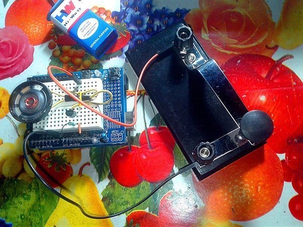
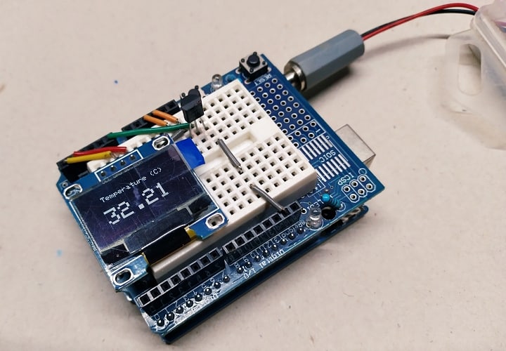
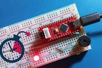
Following is a pair of casual snaps of my hardware lash-up:
Getting back to the loudspeaker driver circuitry, the driver transistor T1 will switch on and off the loudspeaker according to the square wave input. The amplitude of the signal appeared across the loud speaker depends heavily on the positive rail voltage VIN fed in at top. This setup does suffice to get you finally on the upbeat as square waves don’t really necessitate ‘harmonious’ amplification, do they?
I didn’t add a path for the inductive flyback current to go when the driver transistor abruptly shuts off. You don’t bother, at this fairly low power, and Notedly in this project, it might not going to fry the driver transistor.
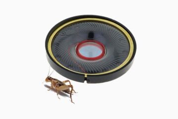
Further, a noteworthy fact is that the major advantage of mylar speaker over the common paper speaker comes in applications where moisture or humidity are considerations. While paper tends to absorb moisture (affecting the mass of the cone with a resulting shift in resonance), mylar is relatively immune to this. An alias for mylar is polyethylene terephthalate (PET) which is used in the pedestrian water bottle. See https://www.stetron.com/loudspeakers-mylar-santoprene/
In conclusion I want to say, I find it can alleviate learning to review what you get over after you get a line on it. So just snap up requisite hardware and start building a portable code practice oscillator with your Arduino. I would love to hear about that in the comments. Let’s make some noise with Arduino!
This was a nice little project. I got the hardware built correctly the first time. My copy/paste of the software didn’t quite work until I realized I had left out a line of code. I would love to see two enhancements: (1) volume control; (2) frequency control. Then, somehow or another I would put this all into a box of some sort and I would have a permanent code practice oscillator.
Joe Berry: Glad it worked for you. I have taken note of your great suggestions and you can see those improvements in the revised version of this post (a few weeks later). Stay tuned. Thanks!
I didn’t need this for morse code practice as I’ve been an Amateur Radio Operator for over 50 years and use morse daily here, but I liked the idea and it is something to loan out to aspiring amateur operators to help them in learning the code. I have made a few minor modifications to both the schematic and program to add both a volume control (depending on the speaker used, it can get quite loud) and a tone control. Most people learning Morse prefer tones higher than the 400 Hz from the original program. I added a 10K Pot from D9 to ground with the wiper connected to the 470 ohm resistor as a volume control and another 10K Pot from the +5 output of the Arduino to ground with the wiper connected to the analog input A0. I changed the program slightly. First, change the line – int keyTone=400; to int keyTone=600 which sets the initial tone at 600Hz. Next, I add one line in the main part of the program, immediately after the “void loop() {” which reads keyTone=analogRead(A0); which reads the pot generated value (between 0 and 1024) to the frequency number for “keyTone” and that’s all there is to it. If you want to limit the low end to, say 400 Hz, just add one more line right after the analogRead and that should read – if(keyTone <400) keyTone=400; and that will limit the low end to 400 Hz.
@Jim sheldon: Thank you for your interest in my article and for taking the time to share your design extension thoughts. Hope this will be of great help to many readers here. Cheers!