Some time ago I had posted a couple of Arduino projects that work in conjunction with external power supply circuits. If you have not already got those ideas yet, you may simply go through the links below to catch them!
This time, I’m going to share another idea loosely related to those little projects. Well, get ready to build your own merest Automatic Shutdown Circuit for Arduino and other similar microcontrollers…
Why another auto shutdown circuit? There are many decent implementations out there in the hobby electronics domain! Any reasons besides the joy of making something yourself?
Well, I wanted to have some features that are not usually noticed in this concept elsewhere. First, I wanted to minimize the components count while building the final version of the auto shutdown module. Also, I wanted to come up with a few more safety measures using some proven closing-off techniques. So, the below circuit allows you to cut off power completely when the microcontroller finishes executing its assigned tasks. Since there is zero power consumption when the microcontroller is not executing any tasks, the battery pack lasts longer than usual in that setup.
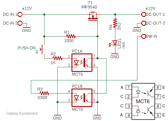
Note at this point that the circuitry is centered around an easily available dual-channel optocoupler (https://www.vishay.com/docs/83645/mct6.pdf) but it can also be stuffed with discrete transistors or optocouplers. Actually, this is a pretty perspicuous design implementation, with nothing special to say about it!
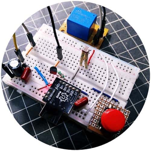
Oh, this is my muddy mock-up pieced on a standard breadboard:
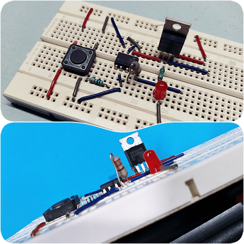
Well, let’s see how the automatic shutdown circuit works…

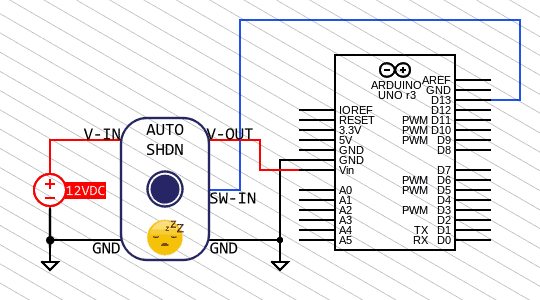
When you press (and hold) the momentary pushbutton switch (S1) for a moment, there is power reaching the input of the first channel of the MCT6 optocoupler (PC1A). So, it gets fired and pulled the gate of the IRF9540 MOSFET (T1) down to ground (GND). The P-Channel MOSFET turns on when its gate is negative relative to its source, allowing current to flow from the input point (V-IN) of the circuit to the output point (V-OUT) which will power the Arduino board (as long as the MOSFET gate is pulled to ground).
To keep the MOSFET alive even after the pushbutton switch is released, the Arduino microcontroller must send a logic-high (H) signal to the switch input (SW-IN) through one of its GPIOs. Power then reaches the input of the second channel of the optocoupler (PC1B). This ensures that the MOSFET remains in its active state so that current flows to the output point to power the microcontroller.
After that, if the microcontroller sets its GPIO to a logic-low (L) state, power does not reach the input of the optocoupler, so the MOSFET does not allow current to flow to the output point, and there is no power feed to the microcontroller. Yes, the microcontroller (as programmed) turns itself down after executing a task!
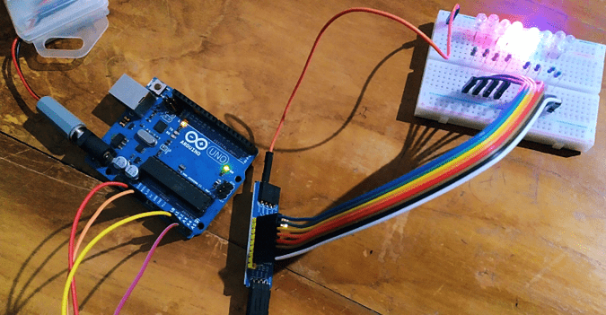
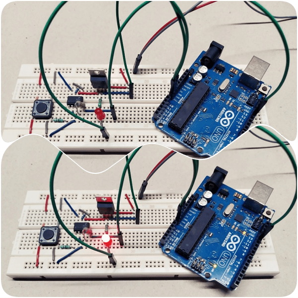
You probably know that there are many ways to create multitasking codes for your Arduino projects. Likewise, it’s fairly easy to set countdown timers and perform tasks in parallel on an Arduino. Doing a little Google search will get you more than you need to get started, so I’m not going into that right now. Anyway, below is a crude code for testing the functionality of your automatic shutdown module with an Arduino Uno (a wiring diagram is also provided to make things easier).
int timer_out = 13; //D13

unsigned long DELAY_TIME = 15000; //15secs
unsigned long delayStart = 0;
bool delayRunning = false;

void setup() {
  pinMode(timer_out, OUTPUT);
  digitalWrite(timer_out, HIGH); //D13 ON
  delayStart = millis();
  delayRunning = true;
}

void timer_off() {
  if (delayRunning && ((millis() - delayStart) >= DELAY_TIME)) {
    delayRunning = false;
    digitalWrite(timer_out, LOW); //D13 OFF
  }
}
void loop(){
timer_off();
}
In this “single-shot delay” code the loop() continues to run without being stuck looking for the delay to expire. During each pass of the loop(), the difference between the current millis() and the delayStart time is compared to the DELAY_TIME. When the timer exceeds the value of the interval, the delay timer is stopped and the D13 output is turned off.
Now you can take a closer look at how the auto shutdown circuit works and how you can use it in your projects with or without further modifications. The underlying design trick is straightforward and self-explanatory. Actually, two “isolated” NPN transistors were connected with their collectors and emitters in parallel which provides a way to turn on the output load via a P-Channel Power MOSFET from two different input signals. Either input can turn the load on, but both need to be off for the load to be off. This is referred to as an “OR” logic function.
You may now have some doubts about the role of the dual-channel optocoupler in this circuit. With a common ground rail for two circuits, an optocoupler is usually not needed (likely it won’t help much in providing galvanic isolation). But every once in a while, you can find designs where an optocoupler is employed even if galvanic isolation isn’t demanded. I’ll get to that later!
OK, that’s all for now. I hope you’ve found this tutorial useful and you’re able to use this idea in your microcontroller projects to save some power. Have fun with your projects.