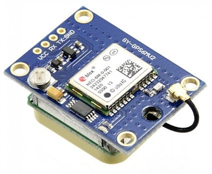
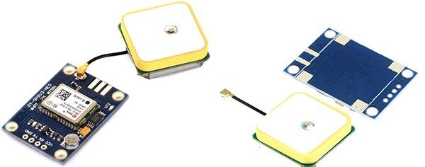
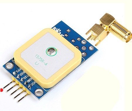
There exist many minuscule GPS-modules suitable for use in microcontroller projects. In this article I will explain how to use the far-famed ublox NEO-6M GPS module with your GPS projects. For a quick start, you can buy the GPS module based on U-blox NEO-6M-0-001 labeled as GY-GPS6MV2 available with a ceramic patch antenna.
Very recently I found another version of the same module named as GY-GPSV3-NEO. It’s in fact an improved universal breakout board for NEO 6M, 7M, and M8N ublox GPS receivers. The new one has an option to mount one SMA connector for external antenna.
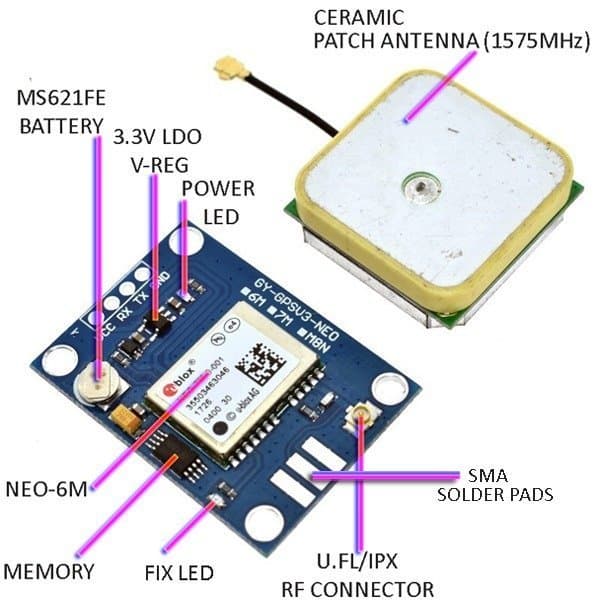
Apart from NEO-6M-0-001, the module has a 3.3V LDO voltage regulator (S2QJ), a memory chip (ST432RK), and one MS412FE (manganese silicon lithium) – compatible rechargeable battery. Besides there’s a red LED for power-on indication and a green LED for position-fix indication. The 1575R-A ceramic patch antenna can be linked to the module through the onboard U.FL/IPX antenna connector. The 4-pin 0.1″ pitch header includes pins needed for communication with a microcontroller over TTL UART.
The operating voltage of NEO-6M chip is from 2.7 to 3.6V. However, the NEO-6M module description says that it’s “5V tolerant”, but it’s mostly because of the built-in 5V-3.3V voltage regulator, I think. I have never seen a NEO-6M GPS module that executes the requisite UART logic level shifting, but the module worked fine without a level-shifter while I was testing it not only with a PC but also with an Arduino (I’ll be back here later).
It’s cheerfully noted that NEO-6M-0-001 GPS receiver can track up to 22 satellites on 50 channels and achieves the industry’s highest level of sensitivity while absorbing only 45mA supply current (Just around 11mA in Power Save Mode -PSM). It can also do up to 5 location updates in a second with 2.5m horizontal position accuracy, and the positioning engine boasts a Time-To- First-Fix (TTFF) of under 1 second. Since the backup battery retains clock and last position, time to first fix (TTFF) significantly reduces to 1 second. This allows much faster position locks because without the battery the GPS always cold-start so the initial GPS lock takes much more time. The EEPROM chip together with the backup battery helps retain the battery backed RAM (BBR) that holds clock data, latest position data (GNSS orbit data) and module configuration. The battery is automatically recharged when power is applied and keeps data intact for up to two weeks without power. For more information about NEO-6M GSM chip(s), check their website at www.u-blox.com.
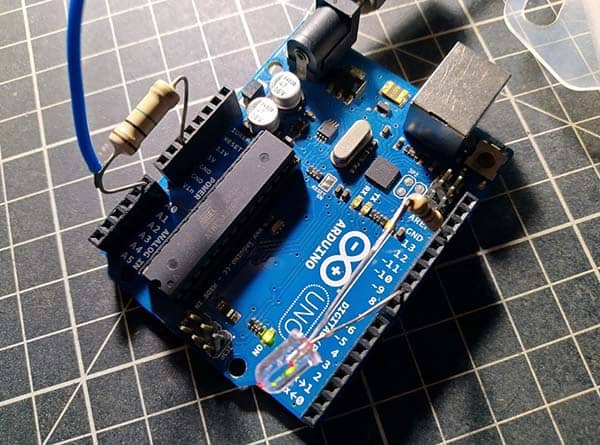
Get it work with Arduino
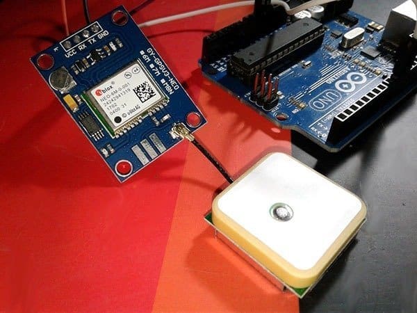
The needed connections to get the GPS module work with a microcontroller (here Arduino Uno) are ground (0V), supply voltage (5V), Tx and Rx. Actually the Rx connection (Tx from the microcontroller) of the GPS module is needed only if you want to send configuration commands to the GPS module. When it comes to UART, the GPS module supports baud rate from 4800bps to 230400bps but with a default baud rate of 9600.
Now start by attaching the patch antenna to the IPX connector. Next connect Rx and Tx pins on the GPS module to I/Os D11 and D10 on the Arduino board respectively, because you’re going to use Software Serial for communication with the GPS module. Finally connect VCC pin of the GPS module to the 5V pin of the Arduino and GND to ground. Well, now you are ready to go!
The blue LED in the NEO-6M GPS module starts blinking at a rate of 1Hz when it can see enough satellites (position fix). If it’s in off state (still searching for satellites), try to orient the patch antenna parallel to the geographic horizon. The antenna must have a full view of the sky to ensure direct line-of-sight with as many visible satellites as possible.
The data you are seeing over the serial interface are actually NMEA (National Marine Electronics Association) sentences (comma separated lines of data). By default, NEO-6M GPS modules update the information once per second (1Hz). Quite often, you need to parse the NMEA sentences into sensible information. To simplify the overall task, you can seek the help of an Arduino GPS Library. For more information about NMEA sentences, go to https://www.gpsinformation.org/dale/nmea.htm
Among other Arduino GPS libraries, TinyGPS++ is a very popular compact library for parsing NMEA data streams provided by GPS modules. To install this library, download it (https://github.com/mikalhart/TinyGPSPlus/releases), unzip the archive into the Arduino libraries folder, and restart Arduino IDE. You should rename the folder as “TinyGPSPlus”. Following is an adapted edition of an example sketch from the TinyGPS++ library.
/*
 * ublox NEO-6M GPS Module
 * Quick Test with Arduino Uno
 * Backed by TinyGPS++ Library
 * Authored by T.K.Hareendran / 2019
 * Published by codrey.com
 */

#include <TinyGPS++.h>
#include <SoftwareSerial.h>
static const int RXPin = 10, TXPin = 11; // GPS Module’s Tx to D10 & Rx to D11
static const uint32_t GPSBaud = 9600;
TinyGPSPlus gps;

SoftwareSerial ss(RXPin, TXPin);

void setup()
{
  Serial.begin(9600);
  ss.begin(GPSBaud);

  Serial.println(F("NEO-6M GPS MODULE QUICK TEST"));
  Serial.print(F("Testing with TinyGPS++ library v. ")); Serial.println(TinyGPSPlus::libraryVersion());
  Serial.println(F("By Mikal Hart"));
  Serial.println(F("Adapted Device Example Sketch"));
  Serial.println(F("---T.K.Hareendran"));
  Serial.println();
}

void loop()
{
   while (ss.available() > 0)
    if (gps.encode(ss.read()))
      displayInfo();

  if (millis() > 5000 && gps.charsProcessed() < 10)
  {
    Serial.println(F("No GPS Module Found! Check Hardware!!"));
    while(true);
  }
}

void displayInfo()
{
  Serial.print(F("Location: "));
  if (gps.location.isValid())
  {
    Serial.print(gps.location.lat(), 6);
    Serial.print(F(","));
    Serial.print(gps.location.lng(), 6);
  }
  else
  {
    Serial.print(F("INVALID"));
  }

  Serial.print(F("  Date/Time: "));
  if (gps.date.isValid())
  {
    Serial.print(gps.date.month());
    Serial.print(F("/"));
    Serial.print(gps.date.day());
    Serial.print(F("/"));
    Serial.print(gps.date.year());
  }
  else
  {
    Serial.print(F("INVALID"));
  }

  Serial.print(F(" "));
  if (gps.time.isValid())
  {
    if (gps.time.hour() < 10) Serial.print(F("0"));
    Serial.print(gps.time.hour());
    Serial.print(F(":"));
    if (gps.time.minute() < 10) Serial.print(F("0"));
    Serial.print(gps.time.minute());
    Serial.print(F(":"));
    if (gps.time.second() < 10) Serial.print(F("0"));
    Serial.print(gps.time.second());
    Serial.print(F("."));
    if (gps.time.centisecond() < 10) Serial.print(F("0"));
    Serial.print(gps.time.centisecond());
  }
  else
  {
    Serial.print(F("INVALID"));
  }

  Serial.println();
}
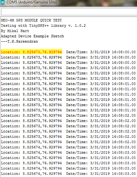
Upload the code and open up the serial monitor (9600 baud) of the Arduino IDE. You should see the output similar to:
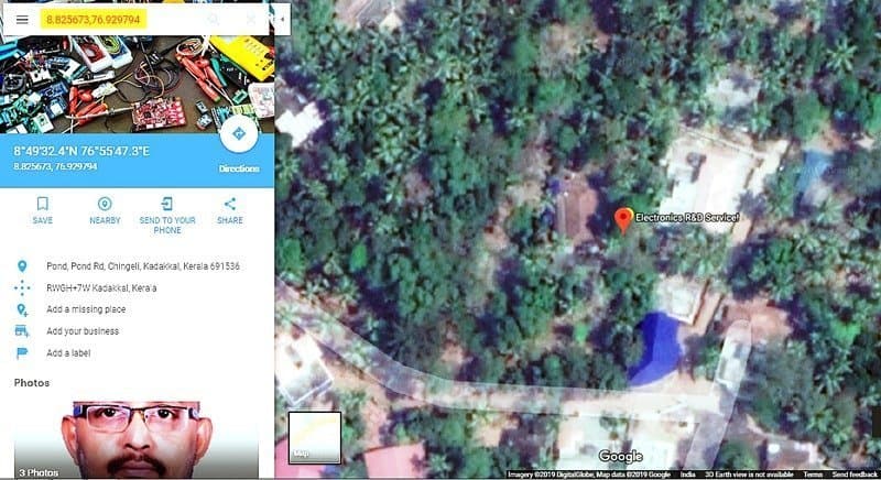
Finally you can validate your NEO-6M GPS module roughly by seeing the Google Map based on the latitude and longitude information displayed on the serial monitor window. That is to say, create a URL like http://maps.google.com/?q=[lat],[long], and go! See the result of this one http://maps.google.com/?q=8.825673,76.929794 (strictly correct).
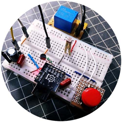
The PPS Signal
Some GPS modules (see next image) today have a digital output signal which changes value on the one second boundary for UTC (Universal Coordinated) time, called PPS. There are two measures of the signal – first is the signal accuracy and the other is its precision. Accuracy is how close the signal edge is to the actual UTC boundary. The second is the precision, which is how much the PPS signal edge changes from one second to the other. The PPS signal polarity and length is usually programmable in the GPS.
And that’s all. Once again I hope you found this article interesting and useful. Your feedback is much appreciated. In the meanwhile have fun and keep checking into codrey.com/author/tkhareendran!

Iam doing a project using neo 6m GPS ,900 a GSM,16*2lcd,an emergency switch. The theme of the project is that on pressing the switch the location must be sent to the predefined mobile number in the code and the same to be displayed on the lcd. Please help me with the code.
@Teja: Not tried such a project yet. Anyway here’s a SIM800L based (and slightly different) project that seems helpful to you. Thanks!
(https://www.instructables.com/id/Homemade-Realtime-GPS-Tracker-SIM800L-Ublox-NEO-6M/)
hi sir i interfaced Neo 6M GPS U-blox NEO-6M GPS Module with node mcu and i get the data from gps module using local wifi but i cant get the latitude, longitude data in bike ride i don’t know what the reason please tell any solution
Thank you
@Satya: I’m afraid I don’t know what else you can try. Without getting more on your construct, it’s hard to offer a right resolution,
Anyway, ensure that the GPS module is a real product (not a cheap clone). And, if you’re powering it up from your vehicle battery, recheck that the power input is a ‘clean’ (noise-free) 12V/6V one. Your signals might be too low, as well.
Further, I noticed that if the GPS module has not previously locked on to satellites, it might take up to 15-30 minutes to get the initial fix (also needs a clear sky view to go). Thanks!
The ublox neo-6 does not acquire any satellites during the initial set up. I have set it up fully powered with full view of the sky, no obstructions and the antenna horizontal with the horizon and let it sit fo 30 minutes with no effect. I used my Garmin to validate satellite acquisition and long/lat data. The Garmin acquires 13 satellites in less than a minute at the same location as the neo-6.
What am I missing. Please advise.
Maris: Since you’re getting good results with your Garmon, it seems like either the module is faulty or the module is in cold start state. Refer this post,and revert with the new outcome. Thanks!
https://lastminuteengineers.com/neo6m-gps-arduino-tutorial/
What is the cold start state and how do I get out of it. Initially it was running connected to an esp32 board via the Arduino IDE on a ubuntu 18.04 linux system.
The Arduino IDE compiled and loaded the esp32 with no problem but returned all 0 for long/lat. I took the system (laptop) outside and noticed that it was still retuning 0. That’s when I isolated the Neo-6 and powered it to see if the prob was in satellite acquisition.
Wrong email. Note correction
Maris: Apart from reading this post once again, you may check out the link given in my previous comment to get an in-depth idea of the GPS module. Cold start is also explained there. BTW I tried my module on Arduino platform only, not with any esp hardware. If you’re getting erroneous output always, then try to restart your tryouts with a new module ftom another vendor. There’re so many fakes in the market!