Recently many readers demanded a simple automatic dusk-to-dawn controller (DTDC) electric switch circuit for real world outdoor/street lighting applications. I looked all the day and finally designed and built this little circuit based on easily obtainable inexpensive discrete components. I’m not all that surprised actually as this is the version 6 (v6) of my design now with some successful trickeries that reduces the overall component count and cost of the construction.
Let’s see its tried and tested schematic first:
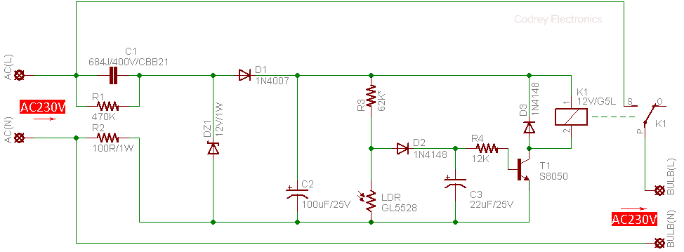
The power supply of the circuit runs on AC 230V/50Hz is a simple capacitor-dropper power supply wired to give constant current close to 30mA only at 12V DC. Key component of the power supply is the 680nF/400V CBB21 capacitor (C1). Next is a half-wave rectifier with one ordinary silicon rectifier diode 1N4007 (D1), and a 12V/1W zener diode (DZ1). The 100uF/25V electrolytic capacitor (C2) is the power supply filter/buffer component. The first 470KΩ resistor (R1) works as a ‘bleeder’ resistor for C1. Besides, the 100Ω/1W resistor (R2) is added not only to limit the inrush current but also to ensure a catchy little circuit protection.
Quite naturally, the ambient light detection is based on a 5mm LDR (GL5528) wired here to form a potential divider with one 62KΩ resistor (R3). Middle point of the potential divider is routed to one S8050 transistor (T1), through components D2 (1N4148) and R4(12KΩ) to turn-on the 12V/G5L (>400Ω) electromagnetic relay (K1) when ambient light level falls below 10lux (and to turn-off the relay when light level goes above 20lux). You can ofcourse change this default on/off thresholds by altering the value of the 62KΩ resistor (R3 = 10KΩ to 100KΩ) but it’s not very necessary in most situations. The 22uF/25V electrolytic capacitor (C3) is there to provide a snatch of hysteresis to prevent the circuit from jittering near the threshold level. The second 1N4148 diode (D3), connected in antiparallel with the relay (K1), is intended to protect the circuits components from possible back kicks occurred during the operation of the electromagnetic relay.
After the successful build of the electronics on a small piece of veroboard (or your own printed circuit board) try to enclose it in a suitable transparent/translucent hard plastic enclosure and make it waterproof. If you want to add a ‘user-control’ potentiometer for sensitivity adjustments in your salable model, then replace resistor R3 with a series combination of one 10KΩ 1/4w fixed resistor plus a 100KΩ ‘plastic-shaft’ potentiometer. Be careful, an electrocution hazard exists during experimentation with this circuit connected directly to the fatal grid power. Since there is no power-line isolation, you must be very thrifty, and an isolation transformer (1:1) should be used when probing the circuit!
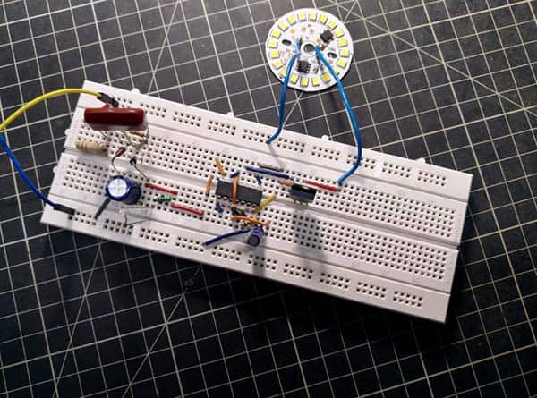
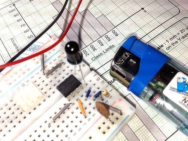
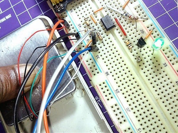
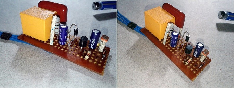
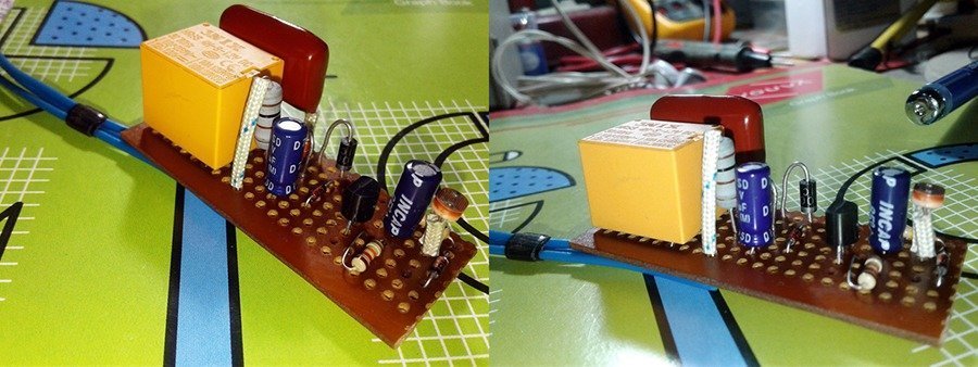
Photographs of author’s prototype built on a rectangular piece of general-purpose perforated circuit board:
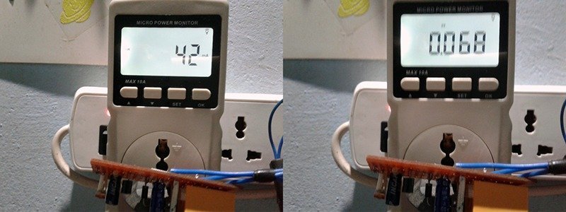
For the most part the prototype draws around 42mA of current from the AC230V/50Hz grid. The observed power factor of the prototype is around 0.068, therefore, so it will register a power consumption of 0.7W (700mW) only (or near to that). Even though it has a very bad power factor, as device operates with a ‘waving’ current that’s extremely low it doesn’t leave much more room for furious debates, we think. As you might noticed, power factor in an ac circuit is the ratio of the true power that is used to do the work and the apparent power that is supplied to the circuit. For more about Power Factor facts, refer https://www.rapidtables.com/electric/Power_Factor.html.
Even though there’s a vast number of ‘photo-switch’ circuits available all over the web indeed, most of them do not work well in real-world (in your lab it will). Besides anyone can publish do-it-yourself circuits in a rush on the Internet. This poses an obvious trouble with using such one to rig up a salable device, as there is no quick way to cognize the credentials of many websites or to get an understanding of the author’s/circuit designer’s level of expertise. However, at the same time, this website is beating as a fountain head of truly tested do-it-yourself circuits and projects readied by adept authors and circuit designers.
This presentation is too be in line with that hard-and-fast policies. After the first ‘enclosed’ build, it’s thoroughly tested in out of doors (to control a driveway light) for around two weeks (it’s still mounted there on the lamp pole). So you can try this little design without doubt, and can transform the basic idea into a salable product. Yes, something will surely have a kick for you!
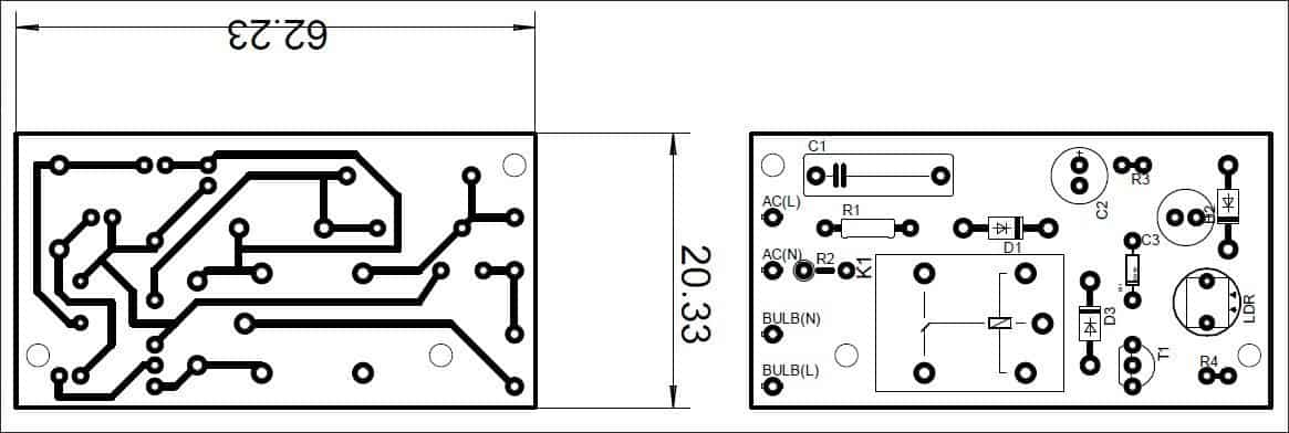
Well, let’s give a small PCB layout designed for home-brewers which with a bit of luck can be fitted in a very small enclosure/ beefy bulb holder. Designing a PCB (whether it’s your first or not) is always stressful. The artwork shown below is just an example, so If you’ve an idea to use your own PCB design, then you must go about it logically and thoroughly check everything you do.
Capacitive Power Supply Maths
It’s worthy to take note that the output voltage of a transformerless capacitive power supply will remain constant so long as current out (IOUT) is less than or equal to the current in (IIN). Just a recap – in our circuit, current in is limited mainly by the reactance of C1 and resistance of R2.
IIN is given by the equation:
IIN = VHFRMS / XC1 + R2 , where VHFRMS is the RMS voltage of a half-wave AC sine wave and XC1 is the reactance of C1. If so:
- VHFRMS = (1.414 x 230)V – 12V / 2 = 157 V
- XC1 = 1 / (2 x 3.14 x 50 x 680×10^-9) = 4683Ω (actual value is 4637Ω because of the presence of R1)
- Therefore IIN = 157 / (4637 + 100) = 33 mA (apprx)
- And VOUT = 12 – 0.6 = 11.4 V (apprx)
In the above calculation, typical values of individual components are used, and their wide tolerances are not taken into account. Theoretically, a 400Ω output load draws around 29mA at 11.4V, and this is near to the calculated 33mA limit. If even more current is demanded by the output load, the supply will stabilize at a voltage below the desired level i.e. the output voltage is compromised. The ripple on output is more pronounced with the increased current draw.
If you carefully probe your prototype by a digital voltmeter, you can see that the power supply output voltage swings roughly between 11.9 volt and 8.9 volt when LDR is exposed to strong light and weak light correspondingly. That’s because actually the circuit needs a current slightly higher than what the constant current power supply can offer. It’s done intentionally here and there’s certain empiric reasons for that. Try to puzzle out it – just a homework for you. And finally note that in theory there is no difference between theory and practice, but in practice there is!