 Recently I got nothing but an inspiration from a pretty nice commercial product “Reflect-a-Bird™ Bird Deterrent” (https://www.absolutebirdcontrol.com/reflect-a-bird-detrerrent). The device from Absolute Bird Control, Inc. is a silent wind-powered spinning visual bird deterrent that effectively scares birds away. Its mirror-like design uses sunlight and wind to create a distraction zone that confuses pest-birds causing them to flee the area. Certainly a silent, economical humane bird deterrent!
A bit of transformation
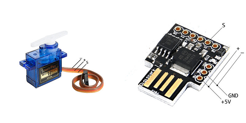
Based on the borrowed idea I unashamedly started a fresh project with the help of one Tower Pro SG90 micro servo and a Digispark Attiny85 microcontroller board on the conscious aim of making an ‘electronic-version’ of the bird deterrent. Well, I got a couple of ideas to move a pair of small mirrors/reflective discs using the servo motor, then I set about making a circuit to control the servo – so I need a circuit which would sweep the servo motor. When it’s completed, I thought others would find the final design useful.
The simple hardware setup
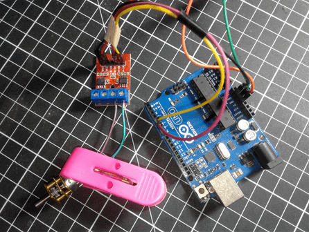
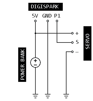
As you can see it’s an ultra-simple design that uses very cheap components and parts. You will need an external 5V dc supply to run the microcontroller board which will also be used by the servo motor – a mobile phone power bank will be a good pick here.
In the hardware, 5V dc supply from the power bank is routed to the 5V header of the Digispark board and the “+” lead of the servo motor. The ground (-/0V) connection is common to the entire hardware. P1 of Digispark supplies drive signal (S) to the servo motor as defined by the little code resides in Attiny85 microcontroller. Since the Digispark board has an onboard red LED attached to P1, we can see the servo pulse activity through it. I have not included a PCB artwork as it is far cheaper and faster just to build it on a flake of perforated circuit board – the so-called veroboard.
A short and stocky code
Below you can find the ‘Arduino Sketch’ for Digispark board. The little code is well commented so that you can see how it plays, or you can conceive it as a good starting point for your own tinkering.
/*
* Code: Servo Sweep (v1)
* Hardware: Digispark & Tower Pro SG90 micro Servo
* Author: T.K.Hareendran/2019
* Publisher: https://www.Codrey.com
*/

#include <SoftRcPulseOut.h> // Required Library
SoftRcPulseOut servo;
int pos = 0;
#define REFRESH_PERIOD_MS 20 // Refresh
#define ITERATE_PAUSE_MS 5000 // Halt
#define NOW 1

void setup() {
pinMode(1, OUTPUT); //P1 as Servo Drive O/P (S)
servo.attach(1);
servo.setMaximumPulse(2200); // See end note!
}

void loop() { // Sweep process
{
for(pos = 0; pos < 180; pos += 1)
{
servo.write(pos);
delay(REFRESH_PERIOD_MS);
SoftRcPulseOut::refresh(NOW);
}
for(pos = 180; pos>=1; pos-=1)
{
servo.write(pos);
delay(REFRESH_PERIOD_MS);
SoftRcPulseOut::refresh(NOW);
}
 delay(ITERATE_PAUSE_MS); // Halt the process
}
The “servo.setMaximumPulse();” function in the above code sets the maximum pulse width allowed for the servo. Note that many standard servos accept inputs from 1000 µs to 2000 µs, with 1500 µs corresponding to the center position. For a 0-180° servo, this would be 90°.
Things to know in front
When it comes to the actual build, as always you should ensure that the interconnections take the right road. Keep an eye on the pin notations of the Digispark and Tower Pro SG90 micro servo as wrong wiring will kill them immediately.
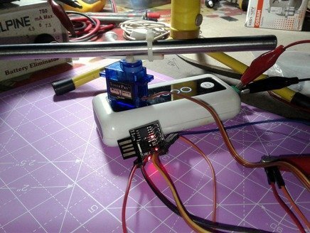
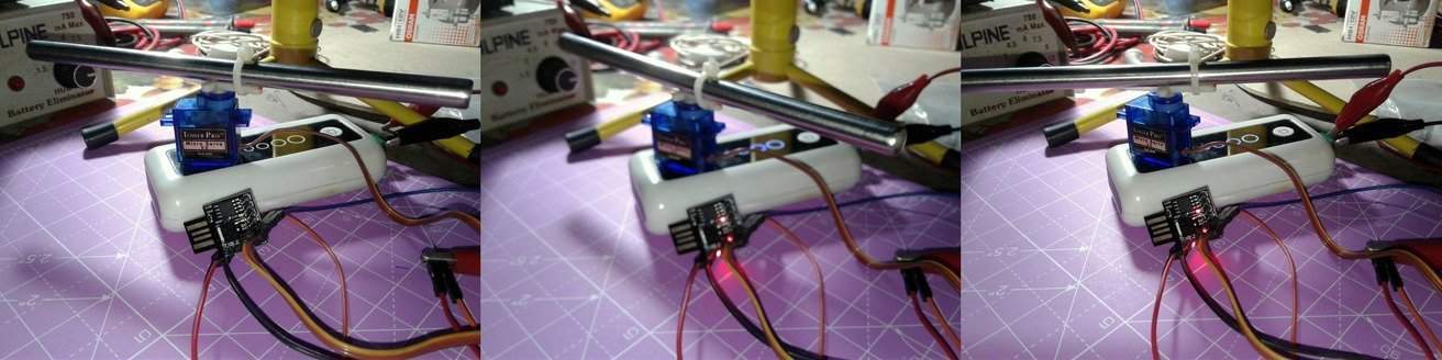
 Likewise, once you have a built the hardware and programmed the microcontroller you should rig up the mechanical section to complete the bird deterrent system. Nowadays small servo brackets are easily available so you can mount the servo up on a suitable servo bracket. Thereafter firmly attach a small tube/stick (with two round mirrors) on the servo horn and finally screw the whole mechanism on a rigid metal base. Next, connect the power bank and power up the system. If everything is okay the servo will probably starts sweeping across the zone i.e. the servo horn will begin travelling from 0° to 180°, coming back to 0°, and after a few seconds, the function iterates. Get it?
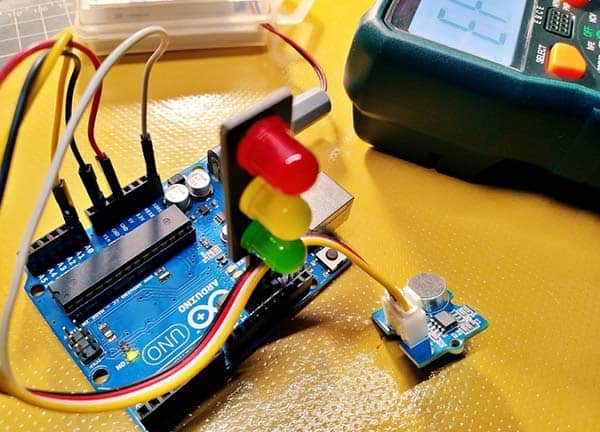
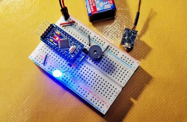
Now I’m waiting for the arrival of a pair of small and lightweight round mirrors for this project. Anyway, here is the mix of a few casual snaps of my successful experiments without the mirrors. It worked easily as anticipated!
Retrace
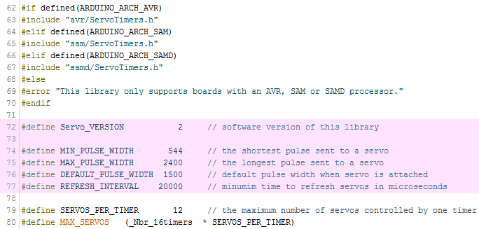
Servo libraries for Arduino (Atmega) and Digispark (Attiny) make it easier to control servos with lighter code and complications. In principle, standard servos expect to see a 1 to 2ms pulse every 20 ms, and the length of the pulse will determine how far the servo turns. A 1500us pulse will make the servo turn to the 90° position (neutral position). If the pulse is shorter than 1500us, then the servo will turn closer to 0°, but if the pulse is longer than 1500us, the shaft turns closer to 180°.
If you was after Arduino’s servo library (& Arduino board) for your experiments, it’s pretty good to configure minimum and maximum servo pulse widths within the ‘attach’ command because it will use the default pulse width values (544 – 2400ms) otherwise. Or play with the library locally to modify the default pulse width values. Admittedly, it’s okay to blindly follow Arduino’s servo libraries, but far better to go through and interpret them before the real play.
Finally, things are perhaps different from the good old textbook lessons in the real world. Therefore if your servo behaves erratically, ensure that you set correct pulse width limit in the code/sketch. Make sure that you understand how servos work before you modify the code/sketch. I’ll try to refine this when I have a little more leisure time.